Mystery 18-FET controller

alpine44

100 mW
Joined
May 1, 2011
Messages
36
Does anybody recognize this controller?

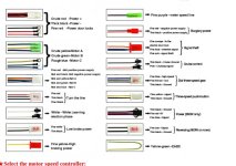
I am trying to figure out the purpose of the connection wires. DC power, phases, halls, throttle, and self-learning are obvious but who knows what the rest is for.

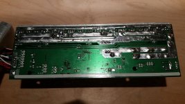
PcbTop_800.jpg
PcbBottom_800.jpg

BTW: How do I make the pictures visible in the text? FIXED: Pictures need to be smaller than 800 pixels on largest edge
 
What are the colors/connectors/thickness of the other lines?

You need to hit the place inline button such that this shows up in your text: "[attachment] yourfilename [\attachment]"
 
cal3thousand said:
What are the colors/connectors/thickness of the other lines?

You need to hit the place inline button such that this shows up in your text: "[attachment] yourfilename [\attachment]"

The colors of the other wires do not match anything I found online from various vendors. I will take a photo when I am back home.

Re: embedded images
I hit the place inline button and have the [attachment] tags but pics do not show until you click the link.
I also tried surrounding the file name with the
 
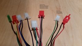
I hooked this controller up to several motors and deciphered some of the feature wires.
See attached picture.

FeatureConnectors.jpg

This controller performs surprisingly well in the sensorless mode (after using the self-learning feature). It managed to start an Invacare GB wheelchair motor against the built-in disk-brake. The brake was partially set to a level that did not allow me to turn the rotor with both hands without using a lever, etc. Nevertheless, the controller got the motor turning in the right direction.
 
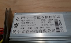
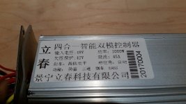
Here is a picture of the label on the controller.
Label_800.jpg

Despite the label saying something about 48V, the controller worked up to 60V (as far as my lab supply could go). It cuts out somewhere around 40 Volt on the low side.


BTW: Embedded images are still hit and miss as you can see at this post versus the previous one. Both are using the [attachment] tag. What am I missing? FIXED: Pictures need to be 800 pixels max on largest edge.
 
Thanks. That explains why some pictures worked and others not. I only paid attention to the overall file size.
 
Have you figured out any more tricks to make this work?

Here is the connection diagram supplied by the seller:

ConnectionsController.jpeg

I just got the 48-72V version and the normal way of connecting things just don't seem to work. Have swapped all the hall and phase wires and throttle wires around, but all I get is a blinking 5v LED on the e-bike tester. Maybe the burglar alarm or the door lock or the burglar alarm wires need to be shorted together?

Plus, the 16 ga battery and phase wires are way too wimpy for a nominal 1500 watt 18 FET 50A rated controller.
 
Update.

That's interesting... It still doesn't work with the ebike tester, but works fine on a motor. I hooked it up to an old Crystalite 408 motor, and it worked fine.. Didn't even have to mix and match hall and phase connectors even without using the self learn function. Color to color.

After hours of searching I did find a review on Amazon that said you have to hook the thin red and black wires (On the far right red connector in Alpine's photo above) (and the 'burglary power' connector in the chart I posted), to the corresponding + and - battery lines, and I tried that, but it is not correct. After getting the controller & motor working, I unplugged them, and it still worked fine. What they do is CARRY full battery voltage, so beware.

The self learn function is interesting and could be dangerous if your wheel is on the ground. Power down, and hook up the white wires, then turn power back on, and immediately the motor spins up to full speed. Twist the controller half way, and the motor stops. Twist to Wide Open Throttle, and the motor goes into reverse, full speed (Reverse 'full' speed is not really full speed, but limited in controller to about 1/3 or 1/2 of what full forward speedis.)

I also unplugged the halls after this, and the motor runs sensorless. I haven't tried to see how the startup torque is sensorless, but it is nice that you could probably make it back home if your motor halls go kaput.
 
I think I may have tracked down the source of this controller:
http://www.focancontroller.com/index.htm
https://www.aliexpress.com/store/group/18-mosfet-1000W/1045372_509289016.html?spm=2114.12010108.0.0.7d847a7XpcDHg

I have a bunch of detailed photos of the insides of the controller, that I'll post in a few days, when I get them sized for the web.
 
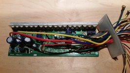
OK I finally got the photos ready to show the details of the inside of the controller, if anyone is interested:

(This is for the 1500 watt controller rated for both 48V and 72V.... I've only tried mine at 48 V (57.8 Hot off charger)

Below each thumbnail is a link to a higher resolution image so as to not waste too much bandwidth.

MC1S.jpg

http://www.az123.com/E-S/MC/MC1.jpg

MC2S.jpg

http://www.az123.com/E-S/MC/MC2.jpg

MC3S.jpg

http://www.az123.com/E-S/MC/MC3.jpg

MC4S.jpg

http://www.az123.com/E-S/MC/MC4.jpg

MC5S.jpg

http://www.az123.com/E-S/MC/MC5.jpg

MC6S.jpg

http://www.az123.com/E-S/MC/MC6.jpg

MC7S.jpg

http://www.az123.com/E-S/MC/MC7.jpg

THE CPU is marked:
GPM813116A0l014
MN68RA
1710


MC8S.jpg

http://www.az123.com/E-S/MC/MC8.jpg


MC9S.jpg

http://www.az123.com/E-S/MC/MC9.jpg

MC10S.jpg

http://www.az123.com/E-S/MC/MC10.jpg

MC11S.jpg

http://www.az123.com/E-S/MC/MC11.jpg

MC12S.jpg

http://www.az123.com/E-S/MC/MC12.jpg

MC13S.jpg

http://www.az123.com/E-S/MC/MC13.jpg

MC14S.jpg

http://www.az123.com/E-S/MC/MC14.jpg

As you can see, there are some small 'bus bars' soldered along the phase traces. Look to be about 1.5MM X 3mm.
MC15s.jpg

http://www.az123.com/E-S/MC/MC15.jpg

Mine is installed in a Chinese three wheel 'pickup truck' with 16S 2P 20AH BatterySpace (GBS) hardshell LiFe prismatic batteries)

So far, It has pulled 2.2 KW for a couple of seconds, and 2.1KW for maybe five seconds. (I haven't put any solder on the shunts to try to increase the amperage), although I did add some bus bars to the major battery power traces... they didn't come from the factory beefed up like the phase traces are. I tested it at WOT for about a mile up a slight grade pulling 800- 1600 watts, and the case stayed cool to the touch... I have a fan on a ~ 90F thermal switch that is Arctic Sllvered to the controller case, and so far the fan hasn't turned on... Ambient temp was about 60F at the time of the test.

I was wrong up a few posts above when I said the battery and phase wires were 16 ga. They are closer to 13Ga.... The insulation is just super-thin. I replaced them with 10Ga silicone wires though.

So far so good. Seems like a pretty good deal for $43.00.
 
alpine44 said:
Despite the label saying something about 48V, the controller worked up to 60V (as far as my lab supply could go).
A fully charged 48v pack would be pretty close to 60v.
 
Ah-ha! After (almost) toasting the identical 1500w/48-72v version I happily stumbled here.

Now that "almost toasted" should give you an idea of how well I was able to decipher wire functions. Motor and battery, fine. Hall effect throttle, that worked too. Hall sensor lines I'm assuming are fine as they match directly to the hub motor I have.

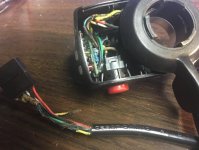
All that said, I'm guessing there's a "connect these two wires for the thing to turn on". I researched and looked and finally guessed and ... guessed wrong. After tearing it apart, it doesn't appear I damaged anything, just melted my throttle cable.
***
scaled_dead_throttle.jpg
***
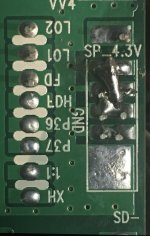
The ones I thought were the "close these and it'll work" are ~ 16 or 18ga. The red traces back to the battery + and the black to what looks like a common ground. (right where it says SP_4.3v on the far right side of the underside of the board)

So what I effectively did was hook up each side to the "on" button on my controller. Which subsequently routed 72v @ whatever amps the BMS would allow straight through those tiny controller wires. Built-in fusing function, I suppose...

However...tracing those wires back and comparing to the lovely reference pix ...something doesn't look quite right. Oh, wait. Yes. That top ground spot is where the black line I shorted was grounded to. It plumb cooked the trace between the pad and the rest of the ground plane, so I jumpered it.

***
fullsizeoutput_d80.jpeg
***

Anyway. Were there proper "short these and it turns on" wires, or am I just likely looking at a controller that perhaps shorted itself long ago. :shock:
 
adbacker said:
The ones I thought were the "close these and it'll work" are ~ 16 or 18ga. The red traces back to the battery + and the black to what looks like a common ground.
If you short battery positive to ground (which is battery negative), then the result you got is to be expected. ;)

It is possible that all of the wires inside the throttle cable are damaged in a way that if it isn't actually shorted now, could fail later with pressure on the outside of the insulation, or tugging on the cable, etc. So I'd recommend replacing the entire run of wire from the throttle to the controller, to be safe.


If there's a switch on the throttle, it can be used for a number of things. One of them is to connect the "keyswitch" or "ignition" wire to the battery positive, making it a "power" switch. The k / i wire is usually a thin red wire taht runs from the battery-input side of teh low voltage section of the controller, somewhere near the input capacitors or voltage regulator, etc.

However, it can be a bad idea to have any battery voltage in the same cable and / or housing as the low voltage throttle electronics. If it gets wet, or something damages the cable, it's easily possible to short the battery voltage to the low-voltage electronics, destroying them--and this means it's also connected to the *controller's* low-votlage electronics, and can destroy them, too. It's happened to people before (there's a number of threads/posts here on ES about it, for instance).

I prefer having the switch on the controller itself, or somewhere close to the main power wiring, or at least somewhere away from low-voltage wiring/parts.

On most of my stuff I wire the k / i wire permanently on and just have a battery-disconnect to totally cut power from everything. Others prefer the opposite, so it's your call which way to do it.
 
So I'd recommend replacing the entire run of wire from the throttle to the controller, to be safe.
The throttle is toast, no doubt. It fused a bunch of internal bits and the wires were pretty spectacularly melted. I've got another one, different model but standard hall effect.

However, it can be a bad idea to have any battery voltage in the same cable and / or housing as the low voltage throttle electronics.
I concur. The toasted controller actually came as part of a 48v controller/wheel/throttle kit, so I'll have to go back to see if that line carried the battery voltage level.

However, at this point I'm just trying to figure out which wires I need to short (if any) to tell the silly thing to turn on. And yeah, I'm inclined to just permanently short the bugger together once I find it.

There is a single red wire that I think qualifies as the "fine red power door locks" in the seller connection diagram. It goes back to the VCC3 point RLT uploaded a pic of:
***
MC7.jpg

***
I tried shorting the red to ground but still am not getting any action. I'm pretty sure I checked it for potential and it was at 0 volts.

Plugging everything in, I measured voltage at the throttle. If it was on, I'd assume there would be +5v between the supply and ground, but there's nothing.

The k / i wire is usually a thin red wire taht runs from the battery-input side of teh low voltage section of the controller, somewhere near the input capacitors or voltage regulator, etc

What would the "low voltage" section of the controller likely be running at? If I locate the VRM, I'm guessing a 5v or 3.3v on the output side? Look for a wire connected near that output and short it back to ground?


Per RLT's comment:
After hours of searching I did find a review on Amazon that said you have to hook the thin red and black wires (On the far right red connector in Alpine's photo above) (and the 'burglary power' connector in the chart I posted), to the corresponding + and - battery lines, and I tried that, but it is not correct.

Pretty sure the wires he's talking about are the ones I shorted through the throttle "on switch". <cough> . I traced and they are indeed going back straight to the battery + and ground, so reconnecting them to battery + and ground indeed is pointless. I think it's likely those are intended to actually *power* the burgler alarm system. Maybe since they carry 72v it's supposed to go to a shock-response. :D

I'd like to determine if it's actually still functional, but I did give in to impatience and just order the 48-72v one that's $50 from Luna Cycles. Community documentation is a wonderful thing... :) . https://lunacycle.com/motors-and-ki...one-mid-drive/40-amp-48-72v-ebike-controller/ . Which also means that, as I fiddle with this one if I accidentally let the smoke out, I still have another on the way...

Thank you so much!
 
adbacker said:
I concur. The toasted controller actually came as part of a 48v controller/wheel/throttle kit, so I'll have to go back to see if that line carried the battery voltage level.
To do that kind of damage, it would have to. ;) The low voltage regulators aren't capable of that kind of current before they'd burn out (or shutdown to prevent burnout).


However, at this point I'm just trying to figure out which wires I need to short (if any) to tell the silly thing to turn on. And yeah, I'm inclined to just permanently short the bugger together once I find it.

There is a single red wire that I think qualifies as the "fine red power door locks" in the seller connection diagram. It goes back to the VCC3 point RLT uploaded a pic of:
It still amazes me how things get mistranslated from Chinese to English, but that is probably the wire--usually it would be "keyswitch" or "ignition", but sometimes "lock", though how they get the phrase yours is listed with I have no idea. :lol:


I tried shorting the red to ground but still am not getting any action. I'm pretty sure I checked it for potential and it was at 0 volts.
That's why I said you have to connect it to battery positive (if it's the k / i wire). If you want to test without frying anything, connect it thru a light bulb (any household incandescent will work). Just hold the battery positive wire against the main screwbase of the bulb, and touch the k / i (powerdoor locks) wire to the tip contact of the bulb.

If the bulb lights up and stays lit, then most likely the thin wire you've got is not the one you want. If it lights fora moment or not at all, but the controller now works, you've found the right pair, and can just connect them together permanently.

If nothing happens at all, and controller doesnt' work, it's possible that the battery voltage short that melted throttle wires also shorted to the 5v line inside the cable, and passed back to the electronics in the controller and destroyed it.


Plugging everything in, I measured voltage at the throttle. If it was on, I'd assume there would be +5v between the supply and ground, but there's nothing.
You won't get anything there until you connect the k/i wire to battery positive, because that supplies the low voltage regulator with power to run.


What would the "low voltage" section of the controller likely be running at? If I locate the VRM, I'm guessing a 5v or 3.3v on the output side? Look for a wire connected near that output and short it back to ground?
No, nothing connects to ground to turn it on. As I said in the other post, the k/i wire would be connected to the battery positive, either directly or via wahtever switch you want to use.

If you search the forums for "ignition" or "keyswitch" wiring, there are a lot of posts that discuss it, some with diagrams and pics, if it helps. (but there's a *lot* of posts with those words, so it could take a lot of poking around to find them :( )
 
Back
Top