Dave's 80:1 RC mid drive kit build log

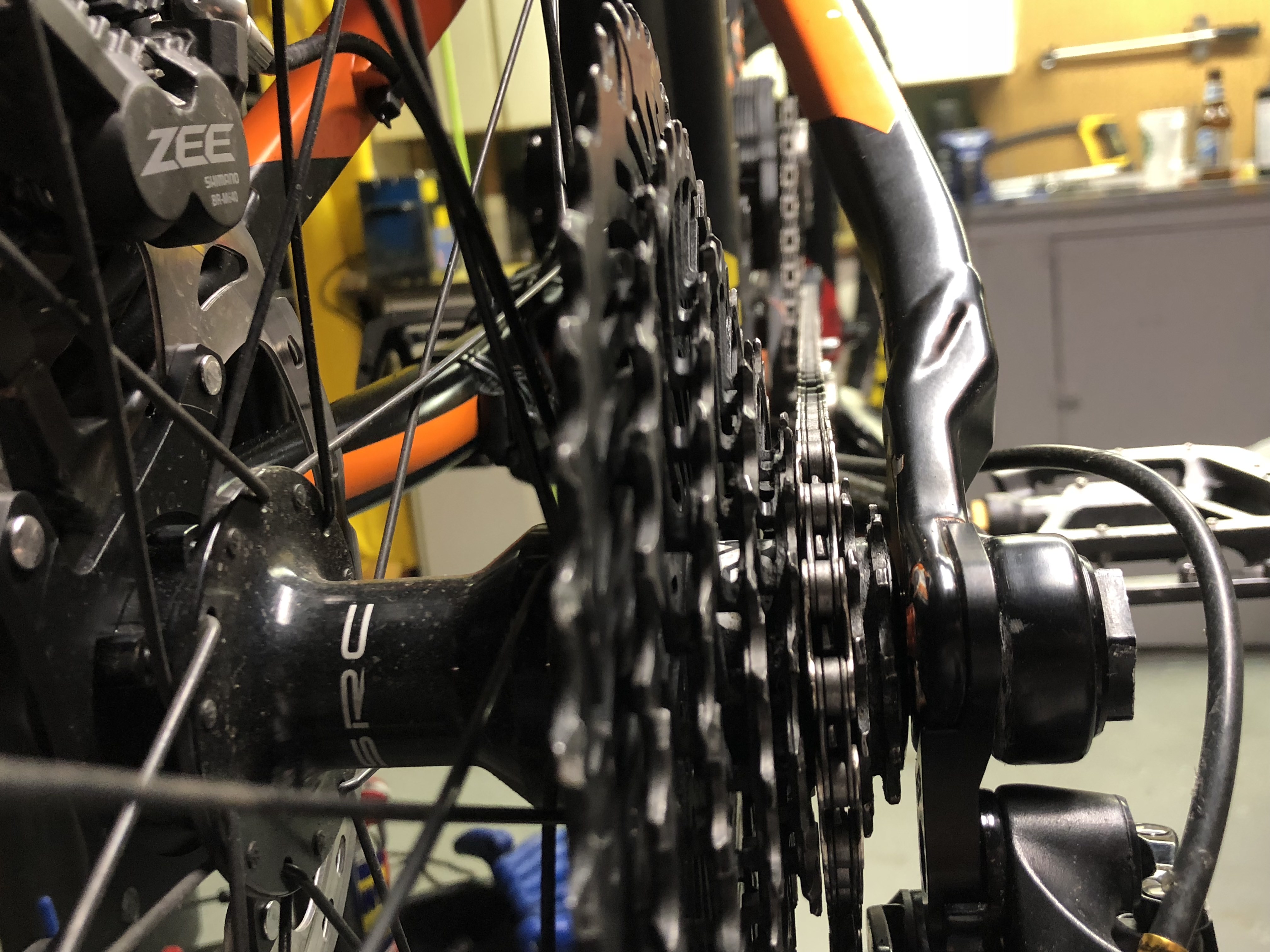
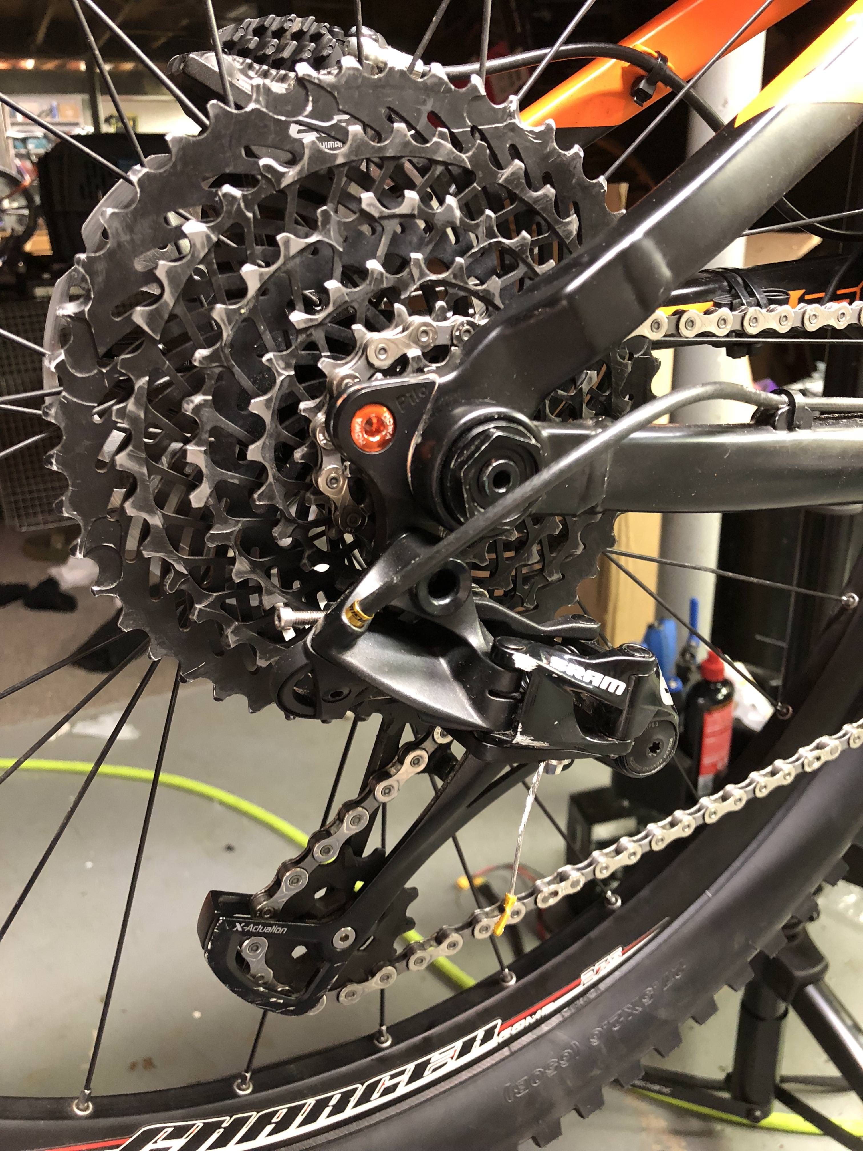
That's your freewheel crankset? If you remove the BB spacer on the drive side, which cog lines up with a straight chain? For the motor, I'd advise the 34t or 32t cog have the straight chain. The Tangent setup will give you about 375 crank RPM at 52V, and on a 27.5" tire that's 34mph (11rpm per mph). 6kW runs well when geared for 30-35mph single speed, so you'll want a 1:1 to the back wheel in the gear you'll use the most (the 30-35mph gear, so the same tooth cog as the front chainring). If the 32t cog is straight chain, that'll allow a couple gears faster or slower with a pretty straight chain to minimize excess wear from high powers.

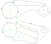
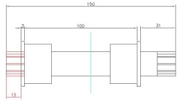
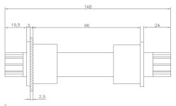
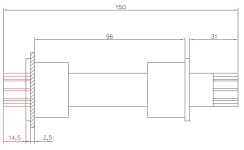
I can add ISCG bolt holes, we'll have to work on the angle between the ISCG standard and where the drive should sit. What's your thinking behind using the tabs to hold the drive unit? The drive side of the frame looks to be flush with the face of the BB. Print out the ESC side PDF and see if it clears the suspension pivot on the left side when the upper cross brace bolt is flush with the bottom of the downtube (the two odd distances on the PDF are where the bolt passes between the mounts and sits against the frame to stop rotation).


On another note, I 'finished' the first of the 3220 housings today with only a minor machine crash. Well, to be accurate, I crashed it into the same same spot twice... This is a very complicated piece, it takes a long time to get the tooling and setup correct and repeatable. Hopefully tomorrow I'll have the CNC code proofed out and the first finished housing ready to receive the 3220 stator. I'll be finishing these kits two at a time, the first several pairs will take me a week each to get in a box for shipping to customers. Things will become faster after a few times through the process.


20180320_204319.jpg


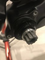
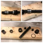
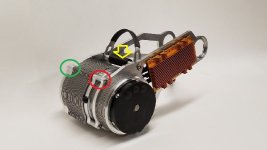
On yet another note, I'd thought I'd share a few pics of the Astro vs the Neu Motor. On paper both of these engines are the same electrically (225kV, 0.019ohm per phase). The Neu is a 3215/1Y, a touch larger diameter, half inch shorter, 6 pole pair, surface mount magnets with a wrap. The Astro is a 3220 3turn, a bit heavier, smaller diameter, 4 pole pair, internally mounted magnets. We know how the Astro performs (effen' awesome), we'll see how the Neu does. The laminations on the Neu appear to be thinner, it's tough to tell.

Astro stator on the left, Neu stator on the right.

20180320_210940_001.jpg
20180320_211002.jpg
20180320_210952.jpg


Astro rotor on the left, Neu rotor on the right (NOTE: strong magnets)

20180320_211625.jpg
20180320_211655.jpg


-dave
 

Attachments

  • Tangent gen2 mount, drive.PDF
    24.3 KB · Views: 73
  • Tangent gen2 mount, ESC.PDF
    22.4 KB · Views: 64
Hey Dave,

Correct this is the freewheel crankset I will be using (Echo with White Ind. freewheel). I'm using a 34T to the back for pedaling and a 32T will be for the Tangent. I'd like to keep the gears for when I want to pedal with the kids. Cog 21T and 23T are more or less straight chainline to the 34T chainring. Was that your question? Removing the BB spacer has minimal affect on the problem of having the 34T drive chainring interfere with the Tangent's drive mount because the mount is "in line" with the bottom bracket cup.

The ISCG-05 tab mount was purely for the chainring clearance... possibly the only way. There's a lot of space between the the face of the ISCG and where the pedal chainring will be. So mounting the drive side mount on the ISCG solves half my motor mounting problem. ESC side and frame pivot is the other problem.

We might have to go custom mounts. I printed the standards and there's no way they will clear the VPP. So I sketched some up, but took a "guess" on your dimensions for the motor mounting holes/geometry (maintained 210,173.89 and 186.88mm). Being your northern neighbour (yes there's a 'u'), I feel some imperial/metric pain :).

Could you tell me the dimensions of the heat sink?

I'll do some more mount tweaking and I could send you the CAD.

Thanks!
 

Attachments

  • Capture.PNG
    Capture.PNG
    8.8 KB · Views: 2,591
I've got mine (which only spins at 275 rpm) lined up with the 15/18T in a straight chain line.
pKDfT4e.jpg


Also, I'm very happy with the combination of the 32T Wolftooth stainless steel drop stop chain ring up front, and SRAM EX-1 cassette that uses hardened tool steel in the back. It's an 11-48 cassette, but I've locked out 11 and 13, so first gear is the 15T.

iBov1JA.jpg

vdYf1E1.jpg
 
Hey FastJohnny,

Nice setup, your mounting brackets don't look like the standards. Did Dave custom make those for your frame, or are they another series offered? Do you have any dimensional details you could share?

Thanks!
 
Leeleeducati said:
Hey FastJohnny,

Nice setup, your mounting brackets don't look like the standards. Did Dave custom make those for your frame, or are they another series offered? Do you have any dimensional details you could share?

Thanks!

Yes they are custom sized to fit in the frame by our man Dave D. I'm not sure of the dimensions, but I will say the super short mounts are both a gift and a curse. The PRO is that they are short, look cool, and fit just perfectly in the triangle. The CONS are that the mounts are too short to mount the ESC on, and make the simple task of running a chain between the motor freewheel and crank chainring a complete nightmare.

Because the mount is so short you can only run certain chainring/motor freewheel combos. I'm going to struggle to explain this. With a longer mount you can run any chainring you want within reason, just take a link out, or add one to get the chain length and tension just right. With my mount, only certain combos work. For example with the 20T freewheel and a 30T motor chainring, using X number of links on the motor chain, it is so loose that the tensioner can't keep enough tension on the chain to stop it from falling off. If I take out a single link of chain, the chain is now too small to fit. If I swap the 30T for a 32T motor chainring, there is now a length of chain just long enough to fit, and the tensioner can apply tension (pictured).
 
Got it! good heads up, I struggled with the same chainlink just one off problem on my other build.
I stuck with the 210mm space between the chainring and freewheel on the mounts I'm thinking of so hopefully I shouldn't have that problem. I also tried to keep the controller still connected to the mount, but I'm waiting for Dave to get back to me with those ESC dimensions before I finalize a design. He must be busy, but great contribution to the hobby!
 
I would have gone with a longer mount myself so I could mount the ESC on it. I’d love to be able to add a cooler to the ESC and run a few more amps. When using the template of the longer mount it looked like the rear shock might pivot forward and hit the gearbox housing.
 
Here's an idea I just thought of.
Regarding the motor chain tension device, I remember fine tuning chain tension on my old KTM 640 was merely spinning a eccentric thing in the rear wheel/axle that moved the axle away. When tension was right, just bolt it down and it was set.
So.. couldn't the whole motor be mounted inside some eccentric thing like that to allow for enough fine tuning of the chain tension, thus eliminating the tension wheel/spring arm? I guess it would add some complexity and weight, but it could possibly eliminate a weak spot. Or maybe it would just need to be too large to be effective as a means of chain tension, haven't exactly done any calculations.
 
knurf said:
So.. couldn't the whole motor be mounted inside some eccentric thing like that to allow for enough fine tuning of the chain tension, thus eliminating the tension wheel/spring arm?

Problem is, after a while, either the chainring or spid r warps slightly and the chain tension changes as it makes a full circle. You can see this when you pedal the bike up on a stand. The chain tensioner will actually move up and down a bit as you spin the cranks.
 
Problem is, after a while, either the chainring or spid r warps slightly and the chain tension changes as it makes a full circle.
Huh, is that so? I do remember a slight variance in tension over the wheel while spinning the cranks (can't check now) but not that much. My wheel isn't that compressed most of the time anyway, it's mainly guiding and keeping the worst slack out. It doesn't drop or cause any problems.
But the tensioner wheel might have saved my large bearings by sacrificing itself a time or two when the chains got horribly tangled up tho.
 
I had to start from the beginning with the bottom bracket. Anyone converting a BB92 or even PF30 to threaded will for sure run into the same problem, it’s not a 100mm, it’s a 96mm as I posted with the adapters and 100mm just won't work. Those few mm’s are critical in making freewheel or crankarm not touch BB cups when tightened. Simply putting a 100mm BB won’t fit.

As you can see in the first picture I tried with a 148x100 FSA BB and because of the freewheel, you can’t tighten the crank bolt without the freewheel making contact with the BB cup. So I tried a spacer and now couldn’t tighten the drive side crank bolt enough to hold the arm on firmly.

The solution was to modify the SickBikeParts 148mm BB. As you can see in the collage, I had to take it apart and add spacers to “balance/center” the 148mm spindle in the 96m dimension with enough clearance on both sides to allow for crank bolt tightening and no contact with crankarm and freewheel. I machined a 10mm spacer on the ESC side and a 15mm spacer on the drive side, then packed in the bearings. It’s balanced now, but still the drive mount looks like it will have to go on the ISCG05.
 

Attachments

  • 2.jpg
    2.jpg
    46.4 KB · Views: 2,429
  • 1.jpg
    1.jpg
    63.1 KB · Views: 2,429
Hi ACeMadMod,

I've already solved the problem, but thanks for the offer.

142 still wouldn't actually work. You need 148mm as a minimum and that alone won't provide the correct centering for the spindle within the bearings and cups. This is why I had to take a 148mm spindle and space it to the correct width and "centering". I say, "centering" because you still need a bit more length on the drive side. I even took into account ~2.5mm on the non drive side for Dave's ESC mount by using a temp. spacer as a placeholder.

Thanks~
 
I still have the XXX. Rode it all of last year, but now it’s time to try something new. I’m really looking for something more “bike” now, super light weight. The Tangent is the best thing on the market for that balance of power and weight. Just have to wait now to get it... Dave? :)) ESC dimensions? :)).
 
Ah, Leelee, it looks as if you need the ISCG bolts to hold the mount against the frame and the cutout for the BB cups will be larger on the drive side. Easy to do with slots like you show. I'll change the ESC side mount to kink downward, lots of bikes have a pivot on that side near the BB so others may need the same design also.

My preference is a spring loaded tensioner, it seems to make life easy when it's working correctly. Constant tension, easy chain removal, allows for one-piece engine mounts. Hate that I have to make it custom and there are random issues until the stupid thing is 100%. FastJohnny is right about some flex- without a spring in the mix, we can lose a bit of tension under full throttle (when we particularly don't want things to fall off) and there can be some wobble in the BB/spider/threaded FW. I'll keep fighting the spring tensioner design for these reasons while keeping an eye out for better ideas


Tangent gen2 mount, ESC heatsink dim.JPG


This is basically the smallest opening that will fit the Talon ESC.


Also, this BB from Lunacycle (https://lunacycle.com/isis-bottom-bracket-68-73mm-for-cyclone/) can be adjusted to fit BB widths 68-95mm. Leelee, the outside face-face width of your BB with the BSA adapters is 96mm, right? Add 4-5mm for the thickness of both Tangent plates and then we'd be at about 100mm. This guy from Luna fits 100+mm wide spacing (https://lunacycle.com/isis-bottom-bracket-100mm-for-cyclone/). I'm setting the chainline for the kits based around these two BB's, with 31mm of spindle stickout on the drive side (end of spindle to BB face). If we use the same spider/FW arrangement, the chainline is repeatable.
 
Hey Dave,

Thanks for the ESC update, but what are the overall dimensions of the heatsink? I'm trying to keep it contained in the mount without overhang.

As for the Luna BB, it will likely not work again as designed. I've attached a sketch for explanation. If the BB is ~100mm and spindle is 150mm and your target is 31mm extension out of the BB cup face on the drive side, there won't be enough spline on the non-drive side to hold the crank arm. The red section marked 13mm in the sketch highlights this, you'd need about 17mm spline and a few mm clearance. We need to take into account the 3mm x 2 for the width of the BB cup which takes away from the overall spindle length.

What I had to make with the 148mm spline protrudes 24mm on the crank side and 19.5-20mm on the other side accounting for a 2.5mm space holder (hatched area on second sketch). There isn't much clearance (estimated 4-5mm) on the drive side space between the BB cup and the freewheel. While sounds like you could still mount a ~2.5mm drive side mount behind the BB cup in that 4-5mm space, it would take from the non-drive side's clearance of (20mm-17mm=3mm), so you'd be looking at zero clearance.

I added a third pic with 96mm on the Luna BB with 31mm overhang, still not enough (17mm) spline bite and a few mm clearance.

And that's why I'm back to a ISCG05 mount on the one side. Yes you'll need a 51mm hole to clear the PF adapter (it's diam. is 50.5ish).

Lee
 

Attachments

  • 150mm.JPG
    150mm.JPG
    18.5 KB · Views: 2,396
  • 148.JPG
    148.JPG
    25.5 KB · Views: 2,396
  • 150mm second.JPG
    150mm second.JPG
    24.2 KB · Views: 2,396
Here's the Luna 178mm wide ISIS spindle with the bearings pushed in all the way. 101mm distance between the cups will work, we can put BB spacers between the cup and mount plate if necessary (plate sits flush with BSA adapters). 31mm stickout on chain side. And look at all that room on the left to cram a cadence sensor on the spindle...if you ever wanna pedal.

Heat sink is 116x60mm.

20180323_115657.jpg
 
That 178mm BB is a beast and great to know it exists! But while solving one problem, it still wouldn't solve them all.

If I'm out 31mm past the BB I still have to bring the pedal chainring back in line with even bigger spacers. An inline chainring puts me past the drive side BB cup towards the frame so I'm exactly back to where I started with the ISCG. Also, if I move the chainring out with the 31mm overhang to allow for the drive side mount then I'm way off in my chainline.
 
Paul D,

That looks very interesting. Make sure there's some good clearance in there between the Eno and the BB cup for tightening.

Dave,

I'm trying to work around your standards and the limitations I'm having with the integration...

* The width dimension the yellow arrow points to is the BB width correct? What widths is this available in?
* It looks adjustable in that could the spacer in the red circle be moved to the green circle side? If it's a 10mm spacer, could I for example machine two 5mm spacers and balance it out?
* What is the dimension you are aiming for for the centre of the tangent freewheel's chainline vs. the face of the bottom bracket cup?
* Are the mounting plates 1/4"? I think you mentioned it before, but what was the machined thickness at the bottom bracket cup 2.5mm?

Thanks again!
 

Attachments

  • iso+esc.jpg
    iso+esc.jpg
    38.4 KB · Views: 2,363
These BB's are heavy, a quality solution is needed Paul D. We do want a freewheel with dual bearings since most of the time it's freewheeling under load. The White HD FW's can work themselves loose, the White UHD or Cyclone FW's are a better choice for us.

The yellow arrow is the basically the BB spacing, this can be whatever. I can buy 10mm and 27mm spacers (for 83 and 100mm) and cut to length for in between widths.
There is 5mm of adjustability in centering the drive, it can be shifted inboard 5mm. The plates are 1/4" thick (6.35mm).
The motor chainline is 19mm off the BB face (the flange the mounting plate bolts to).


20180323_154658.jpg
20180323_154645.jpg
20180323_154820.jpg
 
Back
Top