• Hello ES! We could use some help to get us past the finish line on building the new knowledgebase for the forum.
    Can you donate? Please see our fundraising page. Thank you!

Key throttle wires

Anio58

🔌 New-ish
Joined
Mar 3, 2022
Messages
28
Hello. I hope someone can help me with this. A brushless controller.
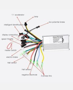
This is a controller I am looking at. It does have a master switch connected to the display.
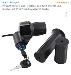
And i have a throttle with a key lock. Can someone tell me for certain what I hook the yellow and the blue wires on the throttle to ?
The switch wire on this controller is connected with the display. So.. do I still connect the blue wire on the throttle to the switch wire on the controller ? And do I splice the yellow wire into the battery positive wire on the controller ?
Photos;
1. Controller
2. Display
3. Throttle
4. Throttle wires connectors
 

Attachments

  • 20221020_143659.jpg
    20221020_143659.jpg
    155.4 KB · Views: 122
  • 20221020_143641.jpg
    20221020_143641.jpg
    89.6 KB · Views: 118
  • 20221020_143322.jpg
    20221020_143322.jpg
    129.3 KB · Views: 116
  • 20221020_143242.jpg
    20221020_143242.jpg
    186.5 KB · Views: 118
In the first photo, you see “master switch”? That is what you wire the yellow and blue to. The yellow will go to your constant hot and the blue will connect to the other wire. I have the same key lock on my bike, just not with a throttle. I might get this exact one for my scooter. I like them.
 
Well,, what color wires should I hook the throttles yellow and blue wires to on the controller ? I do see the master switch.
 

Attachments

  • 20231227_164218.jpg
    20231227_164218.jpg
    355.9 KB · Views: 7
  • 20231227_164111.jpg
    20231227_164111.jpg
    184.4 KB · Views: 10
The RED wire loop will be replaced by your new throttle’s key switch. Remove connector, or cut RED wire in half, and splice wires.
The PURPLE wire going into that connector from to controller goes to the throttle’s YELLOW wire. With the throttle’s BLUE wire connecting to the display’s RED wire.


Regards,
T.C.
 
The RED wire loop will be replaced by your new throttle’s key switch. Remove connector, or cut RED wire in half, and splice wires.
The PURPLE wire going into that connector from to controller goes to the throttle’s YELLOW wire. With the throttle’s BLUE wire connecting to the display’s RED wire.


Regards,
T.C.
Would or,, should I still use the original display with the controller that turns the bike on and off and all settings, or do I just use the display on the throttle which should show voltage ? It does say this about this specific throttle.
Installation method:

With the car key switch, yellow wire connected to the battery +, blue line controller car key switch wire +.

The car key switch can not be used directly as the main power switch. Otherwise it will burn the wiring harness! Remember! The key switch is to turn on and off the power supply of the vehicle by controlling the internal electronic switch circuit of the controller.
 
If you don't leave the controller's display connected to the controller, you can't use anything but whatever the default power-on assist / etc is. Any system settings that are held in the display (vs the controller) will not be implemented.

So if there are any things you need to be different from power-on defaults, you have to have that original display still connected as before.
 
The key switch is fine for switching the on/off circuit on an LCD display, using that connector with the jumper. That's not high current, They're telling you not to be using it for switching the power lines to the comtroller.

The other part of your question. Your picture shows the throttle connector with red, white and black wires, but it appears to be a three pin male JST connector just like your throttle. You can splice directly, but I'd look for a female three pin JST plug and splice that on one of the ends. Buy them on amazon.
 
The key switch is to turn on and off the power supply of the vehicle by controlling the internal electronic switch circuit of the controller.

This is exactly how it's used in place of the "Master Switch" RED looped wire in your application. So no worries!
It may seem a bit counter intuitive to be switching full battery voltage at a throttle location. But as mentioned, the "Ignition, Key Switch, Master switch" type circuits are a very LOW amperage circuit, generally below 100 milli-amps. And how it is done.


Would or,, should I still use the original display with the controller that turns the bike on and off and all settings, or do I just use the display on the throttle which should show voltage ?

I also would recommend using the display... hey, who doesn't want a speedometer? ;)
And an almost must have if using the Pedal Assist System. (PAS)
With full control over controller settings whenever desired.

The only possible downside I can think of for the truly lazy is the 2-stage start-up procedure...
Key switch "ON".
Then press and hold the display "ON" or Power button.

I myself use a 3-stage start-up procedure... which for security reasons I won't divulge. :p


Regards,
T.C.
 
Back
Top