TommyCat
10 kW
How to make a Momentary push button switch work for throttle operation...
How hard could it be?
An informational thread by Tommycat.
July 7th, 2024
But you can also use the information that follows to create a "walk" speed switch or button for something similar.
As the title suggests, this thread will concentrate on what is required to have a momentary push button switch in the normally open configuration, take the place of a hall sensored throttle. In a strictly full off, to full on (or to the choice of motor speed you desire when pressed) manner.
Notice the recommended choice of momentary button switch for the activating component, which requires manual operation to keep the throttle engaged.
If you're thinking about a rocker or toggle type On/Off Switch... consider safety here. A typical "cruise" controller holding circuit will give multiple inputs to disable it. I.E. Braking electrical cut-out switch, cruise button press, or change of throttle position for examples.
So having the throttle manually stuck in WOT may not be a wise choice.
Please make sure your mechanical brakes and brake electrical cut-out switches are working properly at all times.
For more on the safety aspect of working with hall sensor throttles, with information on how, when, and why they work...
As well as importantly showing you how to test voltage and current readings, please read thru this thread first.
Guide to Hall Sensor Throttle operation, testing, and modification. - Electricbike.com Ebike Forum
I recommend that during all testing fully SECURE your bike from moving with the drive wheel free. This is important with all, but with heavier higher powered hub motors that will induce torque jolts... take no chances.
Make sure you understand and respect all the consequences and hazards of working on your bike's throttle input before trying any recommendations.
Remember, there are EXCEPTIONS to everything in the wide world of E-Bikes. In the following thread I'll be speaking in general terms on typical settings and setpoints, and doing a bit of rounding for currents, and voltages ECT.
Also specifically using the data points from my Magic Pie V5 internal controller as examples to illustrate throttle to controller operation. With information that will help you do the same with your specific system.
- On/Off... What's so hard about that?
Your typical hall sensor controller is looking for a throttle input signal of less than 1vdc at the home or off position. Up to WOT (Wide Open Throttle) signal of around 4.2vdc, or in my Magic pie's case, 3.6vdc.
A typical hall sensor throttle will output .8vdc @ Home, up to ~ (around) .9 volts LESS than the Vcc input voltage to the hall sensor when at W.O.T. Often controllers will have a Vcc pad just for the throttle that may output 4.3vdc or so, which is less than a typical 5vdc regulated control output. I've seen some throttles that also incorporated a resistor on the voltage input wire to the throttle's hall sensor that reduces the voltage provided to the hall sensor to a lower amount.
Controllers may also include lock-out safety protection features if it thinks that the throttle signal inputs it is receiving are abnormal, or out of range of valid voltage signals. Possibly caused by an incorrect throttle type being used (I.E. Potentiometer type), damaged throttle, or somebody monkeying around with the throttle signal.
Here is a graphic that illustrates these several points, that one may have to consider depending on your controller.
I recommend you make a chart like this, or at least write down its operating characteristics to give you a clear and straightforward picture of your controller's throttle input requirements and behavior.
Using the single circuit wiring diagram shown further down below as reference and with your normal throttle removed. Use a 200K ohm mini-pot and momentary push button switch (Normally Open) in series between your testing voltage power supply's output and controller's throttle input.
I recommend testing the current draw of this test circuit before use on your system to make sure that the wiring is correct, and no abnormal strain is on your power supply.
Then having your rig secured and testing circuit inline, power up your bike's system, and then your testing circuit's independent power.
From the highest resistance on two of the pot's legs, slowly reduce the resistance to increases the output voltage.
And while monitoring your output voltage meter, write down the important thresholds that you see. Throttle low voltage lock-out, motor starting voltage, motor maximum speed voltage, and throttle high lock-out voltage.
Cycling the momentary switch at all positions to check for proper motor start up in the operational voltage range. Making notes on problems if, when, and where they happen.

From this you can see what an On/Off circuit would need to emulate in order to be successful at fooling this controller.
Starting in the middle of the GREEN zone below and ending in the middle of the GREEN zone above.
Note: Some controllers with programmability may allow you to tweak these setpoints to your advantage if available.
- O.K. What circuit can make this happen?
The trick is in finding the correct resistances for the resistors...
In my case I like to use mini potentiometers and a breadboard circuit testing set-up to quickly and easily lay-out a working circuit that hits the setpoints established above. Using this testing circuit to replace my throttle by using my wiring schematic for the correct pin locations. And adjusting the potentiometers as needed to dial in the desired starting and ending voltages. For me was easy, precise, and no math.
It can be kind of a moving target, as one resistance will influence the other, and vice versa. This was done with the bike and controller powered up and operational as signal inputs will sometimes very between a powered controller, and one that is off. Especially if trying just a one resistor circuit. (See below...)
I also choose to use an external power source during testing as I have no desire to chance damaging the controller's 5vdc regulator.
I recommend monitoring these three things if possible while testing... input voltage, current into circuit, and output voltage.
Once having the potentiometers set to the desired results. I removed them and carefully take resistance readings for the individual resistors, so that these values could be passed along. Feel free to keep the pots in place and have the ability to vary the setpoints at any time, to what you may desire.
Note that when completed, one can also add this on/off circuit to an existing throttle. It's not a case of one or the other. In this case just the high voltage resistor and momentary switch would need to be added, with the throttle covering the home or low voltage requirement. (If needed)
In case you missed it and are interested, a bit more about double throttle operation can be seen here...
Guide to Hall Sensor Throttle operation, testing, and modification. - Electricbike.com Ebike Forum
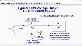
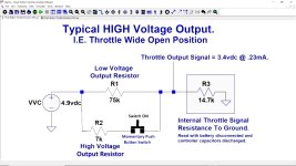
With the values of the resistors determined I then made a model in LTspice to verify the voltages and current readings I was getting. This is where the circuit schematics below came from.
Here is a look at my typical test bench set-up.
For my specific controller, this is the solution for the resistors, and how I would enable them that I came up with.
For a TWO resistor circuit, that should work for most systems solution...


This circuit is tried and tested, and it works perfectly with my specific controller. By changing the R2 resistor, you can change the "high" speed to any voltage (speed) amount desired. Even to just above the motor start level, for say, to enable a "walk" speed. In this configuration there is no hesitation or issues in motor operation between switching between Off and On. (Or "low" and "high" voltage setpoints.)
- How to customize or determine the resistor values for your specific controller, possible short-cuts.
Determine your exact controller requirements and determine resistor values as mentioned above...
Or if desired you could try a few short-cuts that may or may-not work. As your controller has internal resistance on the input signal's line, current will be kept at less that .4mA automatically. Sharp eyes will have seen this in the LTspice circuit schematics.
I would encourage you to test for this resistance before testing to verify.
With the battery removed, and the controller drained of all its stored capacitance voltage. Remove throttle and take a resistance measurement between the controller's throttle input signal and its throttle ground. Mine is 14.7K ohms. If you'd be kind enough to share your internal resistance reading, I'm curious if all controllers are somewhat similar.
With existing throttle removed, possible short cut examples or tests are...
For fun, grab a button cell 3vdc battery and using the correct input locations on your wiring for the throttle...
Wire the negative side of the battery (verify polarity, I find button cell batteries upside down.)
This can also be used to verify that your controller is operational.
In case you missed it...
Guide to Hall Sensor Throttle operation, testing, and modification. - Electricbike.com Ebike Forum

Or try switching the positive power provided (5 to 4.3vdc or there about) directly to the signal input. As mentioned above, I would use an external power source for all testing, but if your careful and don't short anything out... your call. If this works for you, terrific!
If still not satisfied, a single resistor in the R1 position as shown below approach can be tried...
Swapping in different resistance values for R1, in the vicinity of what I required, will hopefully get you where you need to go.
Some notable issues when using the single resistor circuit on my controller...
It will set an error code that will disappear when the button is pushed. (Throttle low-voltage error)
The resistances between a double and single resistor high voltage circuit are different. In the single resistor circuit, a higher voltage output (I.E. lower resistance) was needed for stable operation.
When testing single resistance circuit resistances providing voltages in the motor's operating range, yet below the motor maximum speed starting point, problems where encountered.
At these voltages an immediate switch to the higher voltage was NOT possible directly after first powering up the controller. Now it could be obtained by "double bumping" the throttle button on/off/on in a quick sequence. (possibly fooling the low voltage error cut-out...) But for me it would not be acceptable.
Hopefully this thread will have been of help in this particular pursuit.
Any questions or constructive criticism are certainly welcomed. But if not sure of any suggestions or wiring mentioned. Please ask BEFORE trying.
Respectfully submitted,
Tommycat
Just some extra notes or thoughts if interested.
My controller's throttle voltage input was higher with regular throttle removed... 4.9vdc instead of 4.3vdc.
A hall sensor itself will consume ~6mA of power, but only about .05mA (Home) to .27mA (WOT) of current, on the signal line. (With controller energized)
It's been thought that perhaps such low current usage could/would be problematic. After testing with current levels far below these levels. I believe that is not the case. But for the same reason would recommend the best connections possible. (I.E. soldered)
Considered using the hall sensor's operational characteristic of allowing high voltage output when losing its ground.
But having to keep the throttle installed, need for a normally closed switch, possibly adding a resistor, and a possible fail-safe liability... I elected to pass.
Last edited:


