Ebike help needed

Tipu20

100 µW
Joined
May 8, 2025
Messages
9
Location
London
Hello All,

My Ebike 36V 250w rear hub motor suddenly stopped working. Initial symptoms are no pedal assist or throttle, no error on the M5 display, I did some troubleshooting and found that walk mode of the Ebike works, I also checked when I press the power button [M] and during this press the throttle the motor spins the rear wheel.

i checked that 5V are going to throttle and if i plug it to the multimeter, i can see variable current when pressing throttle (it’s thumb throttle) which indicate good signal, i checked that PAS green light flashes when turning the crank, M5 screen is set to electric drive mode And it doesn't seems to be an issue with P9, P10 settings of M5 display.

When i hooked multi meter to ground and one of the phase wire coming out of the controller, i can see it’s giving good DC volt not sufficient to drive the motor, however the moment i press the throttle the voltage turn to under 2 volt AC current ( i am using auto sensing multimeter). All the cables are tightly connected and none of the cable internally on the controller board is disconnected/broken. I also changed M5 Display with another one and observed the same behaviour. I have checked another e-bike where when i press throttle and connect multimeter to motor phase wire and ground, i get decent DC current.

Why the current will go into AC mode?

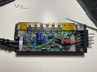
It looks like a controller issue however when i tested the MOSFETs(6) of them they are not shorting with -ve or +ve. Any suggestions what i can look further?

Regards, Tipu
 

Attachments

  • IMG_7236.jpeg
    IMG_7236.jpeg
    2.2 MB · Views: 15
  • IMG_7157.jpeg
    IMG_7157.jpeg
    1.7 MB · Views: 14
Solution
Yes it;s inside the battery, i bought another similar controller and connected with battery terminals however there was no power to the motor or display, might be bad controller, ordered the whole new kit.

I also did some more troubleshooting and found that if i bypass LCD by shorting the blue and red pin on display port and then plug the battery, it now have the pas and throttle both working. I replaced the M5 LCD with another one but that still didn;t help.
I didn't mention that bypass trick, but it does add a new twist to the clues. Not familiar with the M5 display at all, but that would suggest a display configuration issue or controller isn't reading the setup commands from the display, but reads enough of them to exit the...
Motor works in walk mode. It spins with throttle, if you hold down the M button. That says motor must be good. You already changed displays. Only thing left is to get a new controller.

If the motor connector is the same on your other ebike, you could try running this motor on the other controller.
Always the risk that a short somewhere in the motor could damage the other controller though. But that is my quick and dirty test for checking my bikes when a motor doesn't work. I cross wire the motor cables between both bikes, but I know the motor wiring is identical because I built them.
 
Thank you , connected the other wheel with the motor to the Ebike controller and it had the same issue, apart From mosfet what else usually go wrong that can exhibit the behaviour DC to AC voltage?
 
You might want to look at this schematic for a KU65 controller (square wave?) sold by BMSbattery.com as a guide to how controllers are designed. All your waveforms are shaped within a microcontroller, The output MOSFETS are probably representative of what's in your electronics.

I've had several controllers fail, due to water ingress. It's not worth my time to learn how to fix it. Not that smart and not able to solder SMT components anyway. Controllers for my DIY bikes typically cost $20-30 USD. I just replace them.


,


ku63_schematic.jpg
 
You might want to look at this schematic for a KU65 controller (square wave?) sold by BMSbattery.com as a guide to how controllers are designed. All your waveforms are shaped within a microcontroller, The output MOSFETS are probably representative of what's in your electronics.

I've had several controllers fail, due to water ingress. It's not worth my time to learn how to fix it. Not that smart and not able to solder SMT components anyway. Controllers for my DIY bikes typically cost $20-30 USD. I just replace them.


,


View attachment 369990
Thank you for consideration and replying. I think i have to replace more than the controller to bring it into configuration where things can be changed easily

i can see many controllers available but most of them have Anderson connectors rather than 9 pin.

Thank you, i will review the diagram to see if this gives me any clues.
 
i can see many controllers available but most of them have Anderson connectors rather than 9 pin.

Thank you, i will review the diagram to see if this gives me any clues.
Isn't your controller inside the battery cradle? That limits you to buying an exact replacement, which you should if you wish to use the old display.

If you have the skills to mount a controller outside on the frame, you take out the old controller, and run the power connections from the new controller to the 5 pins in the battery cradle, Your will also need to buy a new display that matches the old controller.

The 9 pin connector you speak of, must be the one that goes to the motor, It is quite common for ebike controllers to use this., Don't be looking at anything that uses anderson connectors to the motor. O
 
A. BLDC motor runs on an AC signal, just like an AC motor does, except it uses a controller powered by DC that changes the signal (via commutation) to output the AC signal.
Thank you but when i tested with the working Ebike, the output from phase wire was in DC, may be different type of controllers.
 
Isn't your controller inside the battery cradle? That limits you to buying an exact replacement, which you should if you wish to use the old display.

If you have the skills to mount a controller outside on the frame, you take out the old controller, and run the power connections from the new controller to the 5 pins in the battery cradle, Your will also need to buy a new display that matches the old controller.

The 9 pin connector you speak of, must be the one that goes to the motor, It is quite common for ebike controllers to use this., Don't be looking at anything that uses anderson connectors to the motor. O
Yes it;s inside the battery, i bought another similar controller and connected with battery terminals however there was no power to the motor or display, might be bad controller, ordered the whole new kit.

I also did some more troubleshooting and found that if i bypass LCD by shorting (don’t try this at home please) the blue and red pin on display port and then plug the battery, it now have the pas and throttle both working. I replaced the M5 LCD with another one but that still didn;t help. During this i tested that motor phase pin is getting good DC voltage when throttle is pressed ranging between 4-33 volt which is good and it’s not sending AC current to motor.
 

Attachments

  • IMG_7364.jpeg
    IMG_7364.jpeg
    206.5 KB · Views: 2
Last edited:
Yes it;s inside the battery, i bought another similar controller and connected with battery terminals however there was no power to the motor or display, might be bad controller, ordered the whole new kit.

I also did some more troubleshooting and found that if i bypass LCD by shorting the blue and red pin on display port and then plug the battery, it now have the pas and throttle both working. I replaced the M5 LCD with another one but that still didn;t help.
I didn't mention that bypass trick, but it does add a new twist to the clues. Not familiar with the M5 display at all, but that would suggest a display configuration issue or controller isn't reading the setup commands from the display, but reads enough of them to exit the default condition where it has working display/throttle,

If you break the Txd line, the controller will get no commands and should go to default mode, but it still might send data back to the display, and you would have the speed and whatever else the M5 picks up.

This is for a different display, but it appears your display uses the same pinout,


jumper3.jpg
.
 
Last edited:
Solution
I didn't mention that bypass trick, but it does add a new twist to the clues. Not familiar with the M5 display at all, but that would suggest a display configuration issue or controller isn't reading the setup commands from the display, but reads enough of them to exit the default condition where it has working display/throttle,


.


.
Yep i am confident that its controller however not able to find a good controller from eBay , amazon or AliExpress which has 9 pin higo connector, or i am finding KT controller for which i have to purchase a display and cost for both them is almost half of buying a full conversion kit, hence i decided to buy most common conversion kit and decided to rip this all out. Thank you for all the help and conversation.
 
I didn't mention that bypass trick, but it does add a new twist to the clues. Not familiar with the M5 display at all, but that would suggest a display configuration issue or controller isn't reading the setup commands from the display, but reads enough of them to exit the default condition where it has working display/throttle,

If you break the Txd line, the controller will get no commands and should go to default mode, but it still might send data back to the display, and you would have the speed and whatever else the M5 picks up.

This is for a different display, but it appears your display uses the same pinout,


View attachment 370044
.
Yes it does looks like the same, so the oddest thing happened, i broke the yellow pin and it;s all working fine however it was not limiting the speed and pas was not changing. No when i connected the original display, it’s all working back to normal.

No idea how but it could be that this broken pin has cleared something in controller.

My ebike is back now, i will update if this breaks again :)
 
Thank you but when i tested with the working Ebike, the output from phase wire was in DC, may be different type of controllers.
It's actually AC; it changes current direction during commutation; that is how 3phase BLDC motors work, by switching the current direction between the two active phases to switch the field direction and pull / push the rotor magnets around.

If you are measuring current between ground and a phase, that isn't measuring anything that is actually happening to drive the motor; you're shorting around one of the phase FET bridge halves with the ammeter and creating an artificial current flow.
 
Back
Top