
• Hello ES! We could use some help to get us past the finish line on building the new knowledgebase for the forum.
    Can you donate? Please see our fundraising page. Thank you!

TSDZ8 OSF (open source firmware)

View attachment 379187View attachment 379188i got the Chinese segger here but all jlink v9+ have theuart to comm ports. Easy way to understand is All the pins on the left have 2 functions each and all on the right are just grnd except a few on the top. The other pic is my bodge £8 usb2uart flasher 😂currently I got my 860c display plug disconnected because I was playing around with my sab controller the other night. But basically the way you're looking at it, bottom pin is ground then rx tx (either this order or swapped can't remember) in the middle then the 5v top. 5v and ground to to the buck converter at the top to the "in" side + and - then the"out" side + goes to display 5v and - to display ground. You need a buck converter and set voltage to at least 30 or display won't work.

1 solution that MAY work for you if u have UART on your segger, you can try power display from your bike that way you can skip the whole buck thing. Don't connect it directly to battery though, you'll need to plug it into controller ports power and splice tx +Rx to your segger I think (if someone can confirm)

Also if I wanna try this way , while u do it get a usb2uart and buck for next time and/or if it fails flash. Mine would refuse to boot to home OR power up alltogether when it failed luckily I could still flash it back to working


I promise this is the very last question. Thanks to your detailed explanations, I now have a perfect understanding of what to do. Thank you so much!

I searched for USB to UART adapters on AliExpress and found so many similar products that I'm worried I might buy the wrong one.

If it's not too much trouble, could you possibly share the name or a link to the specific product you used or would recommend? I would feel most confident buying the exact one you suggest.

I'm sorry to keep asking questions, and I sincerely appreciate all the help you've given me. Thank you again!


I promise this is the very last question. Thanks to your detailed explanations, I now have a perfect understanding of what to do. Thank you so much!

I searched for USB to UART adapters on AliExpress and found so many similar products that I'm worried I might buy the wrong one.

If it's not too much trouble, could you possibly share the name or a link to the specific product you used or would recommend? I would feel most confident buying the exact one you suggest.

I'm sorry to keep asking questions, and I sincerely appreciate all the help you've given me. Thank you again!
Here's my exactly item I bought(usb2uart) Youmile CP2104 Module USB to TTL UART Module Serial Converter CP2102 with pin header Dupont cables USB extension cable,for Arduino Raspberry Pi : Amazon.co.uk: Computers & Accessories
And buck converter
 
Have you test run the wheelie build yet? 😆(Don't if your BMS is less than 30 amps tho but I can make a slight nerfed version incase)
I haven't tried it yet. I was mostly just testing a couple of 860c displays I got off ebay super cheap (36usd for two of them!), wanted to make sure they at least powered on.

Honestly I'm pretty boring when it comes to ebikes, :LOL: I just put them on cargo bikes and I'm looking for well tuned and reliable. I usually end upturning them down a bunch 😬:LOL:, I just love the torque sensing assist for getting up hills or putting some distance. But I love pedaling and mostly ride analog bikes. I'm also just a big fan of opensource, I love to tweak things and it keeps hardware usable longer, so it's super exciting follow along with this osf development. All that said, I might give your version a a try soon.
 
They will probably all work. For example, this one definitely works: I just found this on AliExpress:
€1.01 | CP2102 USB 2.0 to TTL UART Module 6Pin Serial Converter STC Replace FT232
Just to add to this, I used a USB to TTL/UART dongle with a ft232rl chip instead of the CP2102 or CP2104 and it worked just fine, so it does seem like any of them would probably work.
 
I haven't tried it yet. I was mostly just testing a couple of 860c displays I got off ebay super cheap (36usd for two of them!), wanted to make sure they at least powered on.

Honestly I'm pretty boring when it comes to ebikes, :LOL: I just put them on cargo bikes and I'm looking for well tuned and reliable. I usually end upturning them down a bunch 😬:LOL:, I just love the torque sensing assist for getting up hills or putting some distance. But I love pedaling and mostly ride analog bikes. I'm also just a big fan of opensource, I love to tweak things and it keeps hardware usable longer, so it's super exciting follow along with this osf development. All that said, I might give your version a a try soon.
Yeah I get ya, when I first went on a ride with this mid drive I was obsessed with the torque sensor I kept stopping still and pedalling to max over and over again 😂
 
Y
Just to add to this, I used a USB to TTL/UART dongle with a ft232rl chip instead of the CP2102 or CP2104 and it worked just fine, so it does seem like any of them would probably work.
Yeah all it needs is to send and receive Rx TX pins really And have the right config loaded which must programs have a library with 100s of preconfigs to make stuff easy
 
Hey, did any of you try to flash the osf using linux? I don't have any Windows machines at home, just mac and linux...
 
I use a Bluetooth module like the HM10 instead of the display to send the interested data to my mobile phone during test rides. You can analyze the data stream afterwards on your PC, or look at the live data on your phone. This helps a lot, to see what happens during real riding.
View attachment 379052


If something like this got implemented, I would be happy to ride around and log data, if it would in any way help the developers.

EDIT: I can solder wires together and implement someone else's code, but I have zero dev skills.
 
If you want to take a look, I created a simple Vesc UART display code for my lilygo s3 here: GitHub - phobos-/VescDisplay
Just added to github. It has been compiled with VSCode with platformio.
thank you! ill have a look round it :)
ive went balls deep through the esp-idf route xD
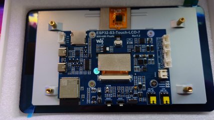
so far i managed toget this screen to switch on with a simple "hello world"
got it to communicate with my motor
started adding in all the tx rx variables, states and all that stuff (basically what ebikeapp.c does)
next steps is making a basic bitch ui to actually get a functional display that can control the controller
hardest part was definitely getting the build enviroment setup correctly and all the hardware drivers/pins configs lol
one thing im really stuck with is finding a decent buck to step down voltage to 5v.
for my first test i made a custom display plug with breadboard pins to stick on the display board for rx tx grd and had my usb cable running downstairs for debugging the display. i used an old key switched throttle to bridge V+ and Vp to turn on the controller but i was scared af doing so as i ddnt wanna pop something had my multi-meter probing all kinds to make sure i wasnt just about to send voltage the wrong way :ROFLMAO: if you know a good buck that can go from 60v+ down to 5v, can provide 2-3a and is small factorid really appreciate it. all ive seen is sketchy looking things withbad reviews of ones the size of charger blocks o_O:ROFLMAO:
 
Id definitely buy an 860c if you're interested in osf. It's not of a nuisance with the normal displays I think. Do you plug your display straight into controller then throttle into display? The top one is the one I use. It came with my motor
Yes my display plugs into the wire coming from the mid drive motor I guess controller and then the throttle unfortunately plugged into the middle of the display along with the remote power and up down buttons
 
Yes my display plugs into the wire coming from the mid drive motor I guess controller and then the throttle unfortunately plugged into the middle of the display along with the remote power and up down buttons
Yeah you just need a different cable then no problem 👍 you can get one with or without the break sensors
 
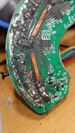
Knew I shouldn't have plugged into pc to debug🤣 co-pilot decided it was a good idea to test a phase resistance by applying 50% duty cycles to a single phase then disable watchdog to try bypass any safety nets 💀oh well lesson learned not to let ai help u debug. Least I can measure any shunts and components to help with real foc development
1000013157.jpg
 
Would it be possible to set the delay time of the shift sensor?

Is it controllable independently in firmware? Or is it just wired parallel with the brake sensor?

I tried looking through the tadz2 OSF threads but I'm not sure it even had a separate shift sensor plug like the tsdz8 does. I never had a tadz2/b.
 
In a system with a torquesensor, you need no shift sensor. Just reduce the force on the pedal during shifting, like you would do on any bike without a motor also. ;)
The tsdz8 has an optional shift sensor. I personally like having it.
You don't need it on a torque sensing motor but it's a nice failsafe for when you forget to let of the power when shifting.
Is it worth 15€, depends on how expensive your casette is.
 
In a system with a torquesensor, you need no shift sensor. Just reduce the force on the pedal during shifting, like you would do on any bike without a motor also. ;)
make sense. does it still apply with OSF when using other mode like power or cadence ?
 
Back
Top