
Power mode is based on torque * cadence. So, if you reduce torque (pedal pressure) , assistance reduce also. This is not the case for cadence mode where assistance is (basis assistance + cadence * ratio). So to reduce assistance you have to reduce cadence and to set asssitance on zero, you even have to stop pedalingmake sense. does it still apply with OSF when using other mode like power or cadence ?

-
Hello ES! We could use some help to get us past the finish line on building the new knowledgebase for the forum.
Can you donate? Please see our fundraising page. Thank you!
You are using an out of date browser. It may not display this or other websites correctly.
You should upgrade or use an alternative browser.
You should upgrade or use an alternative browser.
TSDZ8 OSF (open source firmware)
- Thread starter mstrens
- Start date

The two I bought have a plug for a shift sensor. It works in stock firmware, but the delay is too long imo. I haven't tested with the OSF yet.As far I know, TSDZ8 has no shift sensor. It is just like the TSDZ2.
You are correct though, not every dealer sells them with the shift sensor plug. PSW specifically states that their US stock doesn't have a shift sensor plug.
Since the plug is there it would be nice to know if we can configure it.In a system with a torquesensor, you need no shift sensor. Just reduce the force on the pedal during shifting, like you would do on any bike without a motor also.
HazzaHodgson
⚡ Regular
I made a clutch system on my firmware that when I activated the brake sensor motor would reduce by 10% duty cycle and use very low amps for a smooth shift and return back once I let go. I don't use brake sensor so thought this would be a fun idea. It only activated if throttles being held otherwise brake would cutoff motor as normal. I couldn't find any info on how the shift sensor is wired up if osf or I would've used thatSince the plug is there it would be nice to know if we can configure it.
HazzaHodgson
⚡ Regular
i checked wires that go from shift sensor to pcb
red to 4.3
black to sc
white to grd
so im guessing its just wired with the brake cut off
some of my main harness wires go here and share pins
red to 4.3
black to sc
white to grd
so im guessing its just wired with the brake cut off
some of my main harness wires go here and share pins
Ok awesome, thanks for checking. I was actually just wondering if you would be able to trace it with your fried board.i checked wires that go from shift sensor to pcb
red to 4.3
black to sc
white to grd
so im guessing its just wired with the brake cut off
some of my main harness wires go here and share pins
That's kind of too bad. Would have been cool if it was a separate input. Like on Toseven.
HazzaHodgson
⚡ Regular
To be honest I'm not actually quite sure. CHATGPT said to me that SC is to do with speed sensor and to not use that pinOk awesome, thanks for checking. I was actually just wondering if you would be able to trace it with your fried board.
That's kind of too bad. Would have been cool if it was a separate input. Like on Toseven.
 idk if I'm confused or they're hallucinating. I'll double check and proper trace when I have chance
I have been repeatedly failing to flash my 860C. This time I tried with a newly purchased 860C.Here's my exactly item I bought(usb2uart) Youmile CP2104 Module USB to TTL UART Module Serial Converter CP2102 with pin header Dupont cables USB extension cable,for Arduino Raspberry Pi : Amazon.co.uk: Computers & Accessories
And buck converter
Hailege 5pcs XL6009 DC-DC Adjustable Boost Module DC3.0-30V to DC5-35V Output Voltage Power Converter Circuit Board Module 400KHz : Amazon.co.uk: Business, Industry & Science
Hailege 5pcs XL6009 DC-DC Adjustable Boost Module DC3.0-30V to DC5-35V Output Voltage Power Converter Circuit Board Module 400KHz : Amazon.co.uk: Business, Industry & Scienceamzn.eu
As advised before, I used a USB to UART (FT232RL, 3.3V). I connected the display directly to the battery (48V +/−) without going through the motor controller. TX and RX were connected between the display and the USB to UART, and GND was also connected.
When I press Connect in STM32CubeProgrammer, after about 3 seconds I always get the following error:
Error: Activating device: KO.Please, verify the boot mode configuration and check the serial port configuration.Reset your device then try again...
It seems that the hardware connections are correct, but I cannot proceed any further.
I am a complete beginner and have only managed to get this far by following AI suggestions and forum comments. Now I am stuck and don’t know what else to check.
Could someone please help me figure out what I should try next
"This is a translated version, so please understand if the meaning is not perfectly accurate."
For information, I put an OSF version for 860C for testing. It in in the github site for 860c in a branch named test2. The hex file to flash is "OSF_TSDZ8_860C_SPIDER_3_V00_01.40.hex" (= version 40 with spider 3 logic).
There are quite many changes (mainly in motor.c).
- jitter on elapsed time between hall transition have been reduced.
- all angles for magnetic flux are now in 16 bits (q8.8) instead of 8 bits. Adding 8 decimal bits shoulld increase accuracy
- at each power on, when motor starts running, hall positions are automatically calibrated
- Rotor positioning is not only based on hall interpolation but also uses some logic to reduce jumps at hall transitions (gap is spread on the next 8 PWM cycle)
- CPU time in ISR used for PWM (19kHz) has been greatly reduced. Some tasks (cadence sensor, wheel sensor, voltage sensor, torque sensor have been moved in a 1khz low priority task.
Be carrefull: I did not yet tried this version on the road but it seems that the motor runs (tested in the house).
If you test it, please give here your feedback.
Please note that at this stage, I did not try to improve the motor efficiency and the power.
In the coming weeks, I will try :
- to further increase rotor positionning (increasing clock frequency from 250kHz to 1MHz
- to implement a full foc logic. This should normally improve motor efficiency.
- if I am not able to implement a full foc, I will at least try to dynamically calculate best lead angle.
- to increase max delivered power
There are quite many changes (mainly in motor.c).
- jitter on elapsed time between hall transition have been reduced.
- all angles for magnetic flux are now in 16 bits (q8.8) instead of 8 bits. Adding 8 decimal bits shoulld increase accuracy
- at each power on, when motor starts running, hall positions are automatically calibrated
- Rotor positioning is not only based on hall interpolation but also uses some logic to reduce jumps at hall transitions (gap is spread on the next 8 PWM cycle)
- CPU time in ISR used for PWM (19kHz) has been greatly reduced. Some tasks (cadence sensor, wheel sensor, voltage sensor, torque sensor have been moved in a 1khz low priority task.
Be carrefull: I did not yet tried this version on the road but it seems that the motor runs (tested in the house).
If you test it, please give here your feedback.
Please note that at this stage, I did not try to improve the motor efficiency and the power.
In the coming weeks, I will try :
- to further increase rotor positionning (increasing clock frequency from 250kHz to 1MHz
- to implement a full foc logic. This should normally improve motor efficiency.
- if I am not able to implement a full foc, I will at least try to dynamically calculate best lead angle.
- to increase max delivered power
HazzaHodgson
⚡ Regular
Have you tried connecting it to pins V+ and grd from controllers display port? I'm not quite sure if connecting it directly to battery is the correct way to go. Also try connecting ground to the usb2uart. Get a bucket converter (boosts voltage from usb up to 30v) then you don't need bike battery that way you can rule out ground issues. Try the apt burn appI have been repeatedly failing to flash my 860C. This time I tried with a newly purchased 860C.
As advised before, I used a USB to UART (FT232RL, 3.3V). I connected the display directly to the battery (48V +/−) without going through the motor controller. TX and RX were connected between the display and the USB to UART, and GND was also connected.
When I press Connect in STM32CubeProgrammer, after about 3 seconds I always get the following error:
Error: Activating device: KO.Please, verify the boot mode configuration and check the serial port configuration.Reset your device then try again...
It seems that the hardware connections are correct, but I cannot proceed any further.
I am a complete beginner and have only managed to get this far by following AI suggestions and forum comments. Now I am stuck and don’t know what else to check.
Could someone please help me figure out what I should try next
"This is a translated version, so please understand if the meaning is not perfectly accurate.jave you tried connecting it to pins V+ and grd from controllers display port? I'm not quite sure if connecting it directly to battery is the correct way to go
HazzaHodgson
⚡ Regular
I took measurements for the PCB and have written code to correctly calculate phase amps rather than guess using battery amps+duty cycle I'll test to see how it goes when my new controller arrives. If successful I'll send you a pull request. Out of boredom Im also playing around with build flags and using toggles to disable some debugging for full release to maybe save some time in the isr. I'll let you know how it goesFor information, I put an OSF version for 860C for testing. It in in the github site for 860c in a branch named test2. The hex file to flash is "OSF_TSDZ8_860C_SPIDER_3_V00_01.40.hex" (= version 40 with spider 3 logic).
There are quite many changes (mainly in motor.c).
- jitter on elapsed time between hall transition have been reduced.
- all angles for magnetic flux are now in 16 bits (q8.8) instead of 8 bits. Adding 8 decimal bits shoulld increase accuracy
- at each power on, when motor starts running, hall positions are automatically calibrated
- Rotor positioning is not only based on hall interpolation but also uses some logic to reduce jumps at hall transitions (gap is spread on the next 8 PWM cycle)
- CPU time in ISR used for PWM (19kHz) has been greatly reduced. Some tasks (cadence sensor, wheel sensor, voltage sensor, torque sensor have been moved in a 1khz low priority task.
Be carrefull: I did not yet tried this version on the road but it seems that the motor runs (tested in the house).
If you test it, please give here your feedback.
Please note that at this stage, I did not try to improve the motor efficiency and the power.
In the coming weeks, I will try :
- to further increase rotor positionning (increasing clock frequency from 250kHz to 1MHz
- to implement a full foc logic. This should normally improve motor efficiency.
- if I am not able to implement a full foc, I will at least try to dynamically calculate best lead angle.
- to increase max delivered power

How do youi calculate phase amps? Do you use the 3 shunt currents? Why did you needed measurements for the PCB? Did you looked at the values of the shunt resistances and those of the operational amp (to calculate the gain).I took measurements for the PCB and have written code to correctly calculate phase amps rather than guess using battery amps+duty cycle I'll test to see how it goes when my new controller arrives. If successful I'll send you a pull request. Out of boredom Im also playing around with build flags and using toggles to disable some debugging for full release to maybe save some time in the isr. I'll let you know how it goes
How come STM32CubeProgrammer and not "APT Burn Tools"? Should it work with STM32CubeProgrammer? I haven't been following along.I have been repeatedly failing to flash my 860C. This time I tried with a newly purchased 860C.
As advised before, I used a USB to UART (FT232RL, 3.3V). I connected the display directly to the battery (48V +/−) without going through the motor controller. TX and RX were connected between the display and the USB to UART, and GND was also connected.
When I press Connect in STM32CubeProgrammer, after about 3 seconds I always get the following error:
Error: Activating device: KO.Please, verify the boot mode configuration and check the serial port configuration.Reset your device then try again...
It seems that the hardware connections are correct, but I cannot proceed any further.
I am a complete beginner and have only managed to get this far by following AI suggestions and forum comments. Now I am stuck and don’t know what else to check.
Could someone please help me figure out what I should try next
"This is a translated version, so please understand if the meaning is not perfectly accurate."
HazzaHodgson
⚡ Regular
How we calculate phase ampsHow do youi calculate phase amps? Do you use the 3 shunt currents? Why did you needed measurements for the PCB? Did you looked at the values of the shunt resistances and those of the operational amp (to calculate the gain).
The board measures current with low-value shunts in each phase (marked R006 → 6 mΩ).
Each shunt’s tiny voltage drop is amplified by an op-amp (MCP6021). The op-amp has a feedback network: Rf ≈ 10 kΩ (code “01C”) and an input resistor Ri ≈ 220 Ω (common on these boards), so the gain ≈ 1 + Rf/Ri ≈ 46.5.
The amplified voltage goes into the MCU ADC (12-bit, 0–4095 counts, Vref 3.3 V).
The physics chain for one phase is:
Copy code
ADC_counts → V_adc = (ADC_counts / 4096) * 3.3 V
V_shunt = V_adc / Gain
I_phase = V_shunt / Rsh = [ (ADC_counts / 4096) * 3.3 ] / (Gain * Rsh)
With Rsh = 0.006 Ω and Gain ≈ 46.5:
1 A at the phase ≈ ~0.279 V at the ADC input.
That’s ~346 ADC counts per amp (12-bit).
Inverse slope: ~0.00289 A per 12-bit count.
Sampling: we trigger the ADC mid-PWM (center-aligned) so we avoid switching edges. We read U, V, W, subtract a zero-current offset learned at idle, and then compute a magnitude (for protection/display). Today we use max(|IU|,|IV|,|IW|) for a cheap, conservative phase magnitude. (Later we can do αβ or RMS if needed.)
—
Do we use 3 shunts?
Hardware: yes, it’s a three-shunt design (one per phase).
Firmware: we sample all three around the PWM center. If we ever only got two in one trigger, we could reconstruct the third as Ic = –(Ia + Ib), but on this board we can read all three.
—
Why we needed PCB measurements
Because the counts→amps scale depends on real parts on your board:
Shunt value (R006 = 6 mΩ).
Op-amp gain (set by Rf/Ri).
ADC reference (3.3 V) and effective bit-depth (we sometimes map to a legacy “10-bit step” scale used elsewhere in OSF).
If you guess any of these, your amps are wrong by that factor. That’s how people end up “current-limiting” at the wrong value or blowing FETs—they’re driving blind.
—
What I actually did in firmware
We keep the existing OSF convention that 1 “10-bit step” ≈ 0.15 A, because other code already expects that.
From the hardware slope above, we added a fixed-point factor so 12-bit counts map into those 10-bit steps:
steps10 ≈ (counts12 * 39) >> 11 (≈ counts12 × 0.0190)
That preserves all existing limits (e.g., 333 steps ≈ 50 A phase).
We also do idle offset calibration (average several hundred samples with PWM off) so “zero amps” is actually zero after bias.

stancecoke
🏍️ Giga poster
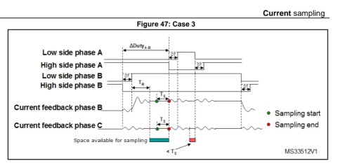
Triggerering at the middle of the PWM period with a quite slow processor only works on low duty cycles. At higher duty cycles there is not enough time to measure under stable conditions, you have to shift the ADC trigger to an area of the PWM cycle where no MOSFET switch happens for the longest possible time. Read only the two phases with the lowest duty cycles, calculate the third from the two measured. Otherwise you get to much scatter on the signal.Firmware: we sample all three around the PWM center.
See chapter 5 of this STM paper
Last edited:
With xmc1302, it is possible to configure ADC and timer in such a way that timer will trigger the ADC. The ADC has 2 groups. It means that it is possible to let xmC1302 to sample 2 channels (= 2 pins) simultenously. There is only one ADC converter and so it will first onvert one of the sample voltage and afterward the other sample. Results are stored in different register. MCU can see if conversion is allready performed and read the result register. So I presume that, even the XMC1302 has a slow processor, this allows to get accurate current phase measurement. Do you see an issue with this solution?Triggerering at the middle of the PWM period with a quite slow processor only works on low duty cycles. At higher duty cycles there is not enough time to measure under stable conditions, you have to shift the ADC trigger to an area of the PWM cycle where no MOSFET switch happens for the longest possible time. Read only the two phases with the lowest duty cycles, calculate the third from the two measured. Otherwise you get to much scatter on the signal.
See chapter 5 of this STM paper
stancecoke
🏍️ Giga poster
That's exactly the same with the STM32.With xmc1302, it is possible to configure ADC and timer in such a way that timer will trigger the ADC.
The fourth channel of the PWM timer is used to trigger the ADC. At high duty cycles, there is not enough time in the middle of the PWM cycle for the AD conversion without having oszillation from the MOSFET switch in the current signal. So you have to shift the trigger point to a slot with undisturbed conditions.
Last edited:

The TSDZ8 has an optional shift sensor and you do need it for proper shifting because there is a delay when you let go the pedals. Alternatively you can halt the motor by pulling slightly on the brake lever (assuming you have installed the brake sensors) and this halts the motor immediately!In a system with a torquesensor, you need no shift sensor. Just reduce the force on the pedal during shifting, like you would do on any bike without a motor also.
I have only used the Toseven DM01 and the TSDZ8 torque sensing motors but that Is what I have noticed as well. While the shift sensor is not 100% necessary, it's really nice. Just easing up on pedal pressure when shifting doesn't quite do it, because the motors have a delay and keep putting out significantly more power then my legs would be. It makes shifting not as seamless as it could be.The TSDZ8 has an optional shift sensor and you do need it for proper shifting because there is a delay when you let go the pedals. Alternatively you can halt the motor by pulling slightly on the brake lever (assuming you have installed the brake sensors) and this halts the motor immediately!
Shifting with the DM01 where you can tune the shift sensor, is so smooth. It's just like shifting on an analog bike. Shifting with the TSDZ8 shift sensor on stock firmware is OK, but it's not smooth, you sort of lurch a bit because the motor power drops for so long.
stancecoke
🏍️ Giga poster
Then the firmware is bad. You can reduce the motor power immediately if a shifting-typical sudden decrease of the torque is detected.because the motors have a delay
I don't know a shift sensor on Yamaha, Bosch, Panasonic.... middrives
Let's say, its not the best..Then the firmware is bad. You can reduce the motor power immediately if a shifting-typical sudden decrease of the torque is detected.
I don't know a shift sensor on Yamaha, Bosch, Panasonic.... middrives
HazzaHodgson
⚡ Regular
It's a lazy cassette protection thing. They'd rather have a slow ramp up to stop motor snapping people's chains rather than implementing a smooth seekerLet's say, its not the best..
The problem is that it's too lazy...It's a lazy cassette protection thing. They'd rather have a slow ramp up to stop motor snapping people's chains rather than implementing a smooth seeker

I completely agree with you and have written about this on the forum here before.While the shift sensor is not 100% necessary, it's really nice. Just easing up on pedal pressure when shifting doesn't quite do it, because the motors have a delay and keep putting out significantly more power then my legs would be. It makes shifting not as seamless as it could be.
My previous Shimano HG50 transmission (chain+casette) lasted 1,000 km without a motor + 1,000 km with TSDZ2B.
As soon as I installed TSDZ8 - the chain started "skipping" from the first day of riding.
Now I've installed Sram PG950 set, and it's very funny that the Shimano Alivio rear derailleur works MUCH better with the Sram transmission. The shifting is much smoother(under load also) than it was with Shimano
Although, it would seem that Shimano should work better with Shimano... but no 
Returning to the shift-sensor: IMHO it is really necessary for powerful motors such as the TSDZ8.
Bit now I use the brakes - before shifting gears, I gently press the bracke lever on the left side, the motor instantly cuts off the traction, I shift gears and - release the brake lever. It really works like a clutch on a motorcycle))
But over time, I'll probably try the shift-sensor... OR - play with the OFS settings.
And do they have the same pulling power as the TSDZ8?I don't know a shift sensor on Yamaha, Bosch, Panasonic.... middrives
Because if so, how come they all have a legal 250 watts rating, while the TSDZ8 has at least 500-600 watts?
Do legal 250 watts pull the chain harder than 500-600 watts of illegal ones? Please explain this, because I really don't understand how it works..)
But the firmware can be good. How about this option?Then the firmware is bad. You can reduce the motor power immediately if a shifting-typical sudden decrease of the torque is detected.

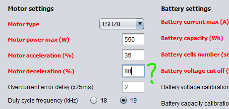
Last edited:
LeoSuperMoin
🔌 New-ish
I completely agree with you and have written about this on the forum here before.
My previous Shimano HG50 transmission (chain+casette) lasted 1,000 km without a motor + 1,000 km with TSDZ2B.
As soon as I installed TSDZ8 - the chain started "skipping" from the first day of riding.
Now I've installed Sram PG950 set, and it's very funny that the Shimano Alivio rear derailleur works MUCH better with the Sram transmission. The shifting is much smoother(under load also) than it was with Shimano
Returning to the shift-sensor: IMHO it is really necessary for powerful motors such as the TSDZ8.
Bit now I use the brakes - before shifting gears, I gently press the bracke lever on the left side, the motor instantly cuts off the traction, I shift gears and - release the brake lever. It really works like a clutch on a motorcycle))
But over time, I'll probably try the shift-sensor... OR - play with the OFS settings.
And do they have the same pulling power as the TSDZ8?
Because if so, how come they all have a legal 250 watts rating, while the TSDZ8 has at least 500-600 watts?
Do legal 250 watts pull the chain harder than 500-600 watts of illegal ones? Please explain this, because I really don't understand how it works..)
But the firmware can be good. How about this option?
View attachment 379789
I had an old mountainbike with a shimano tourney rear derailleur. It was a cheap mountainbike but was fine since it was used as a gravel bike. The chain, derailleur, cassette survived and were still acceptable after 5000km.
Then i installed the tsdz8 on the bike to test it before doing a build with it.
After around 200km it destroyed my cassette and chain.
I thought it was just the age of the the parts. I got a new cassette and chain and after around 250km it destroyed them again.
Then I installed my new Acera rear derailleur along with another new chain and cassette (the cassette was still acceptable but i replaced it to be safe). The bike has now been running for 1500km and both the chain and cassette are still good.
I guess don't cheap out on the derailleur.
Similar threads
- Replies
- 44
- Views
- 1,427
- Replies
- 16
- Views
- 3,734

- Replies
- 4
- Views
- 3,790
- Replies
- 5
- Views
- 7,214

- Replies
- 102
- Views
- 14,985