Nanjing Fardriver CAN-BUS addition/conversion

Joined
Aug 29, 2024
Messages
18
Location
Fort Wayne, IN
I've been exploring what's possible in configuring the CAN-BUS on a non-CAN unit (specifically an ND84530). With the PC app, I've found that setting Monitor -> CAN to CAN1-60 outputs a signal on the low-speed sense line (PIN5 in the PC app). If I change the CAN baud rate, I can see the signal change on my oscilloscope. I imagine that this talks to a transceiver (PIN5 being the TX), and have guessed that the high-speed sense line is the RX (PIN15) - some documents mention that these lines aren't available on CAN units. The signals sent on PIN5 seem to be low-pass filtered (needed for a sense line, no doubt), but this prevents the line level from reaching the threshold to be detected by a transceiver. I would imagine it's easy enough to open things up and remove the low pass filter from the line(s), but haven't gotten to that yet. Has anyone tried such a thing yet, or have more knowledge of how the CAN system works natively?

Also, if anyone with a CAN-enabled unit would be able to share CAN parameters from the PC app, that would be great - I've experimented a bit with the variables according to the "additional parameters" documents I've found, but so far I haven't been able to get any actual data sent out via the line, or get the signal to change at all.

The line is 3.3V, and signal (which seems to be serial) that's sent (via pull-downs) seems to be one long followed by 16 shorts. I imagine this could also be an initialization for the transceiver since I haven't been able to get any data encoded, but I haven't researched much about that yet. I'm hoping to find a teardown of a CAN-enabled unit to see what it looks like.

These are how often the signal is sent for the different CAN baud rates - the CANDelay didn't seem to affect them at all:
CAN 250K: 135 Hz @ 9600 Baud
CAN 500K: 270 Hz @ 19200 Baud
CAN 1M: 540 Hz @ 38400 Baud
 
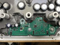
I've taken things apart & can confirm my controller (ND84530_24_ABH64 Type S30) uses a GigaDevice GD32F303CCT6A. I've removed some of the potting & gotten the daughterboard off of the mainboard. Unfortunately mine was soldered instead of slotted, with three 2mm 2x5 connectors. I've documented all of the connections from those to the MCU & 30pin connector here: fardriver-controllers/README.md at main · jackhumbert/fardriver-controllers

I'll have some photos soon, but I'm going to remove the input filtering from the High/Low Speed lines (A11 & A12) to see what kind of signal these use. I have a CAN Pal that I want to connect, but I'm not totally sure what these use to talk to each other. It seemed like it was outputting serial with those precise bauds, and I haven't found anything regarding that in the documentation.

I'm kind of thinking that the input filtering (which includes some RE7 diodes) prevents the MCU from initializing the CAN/receiving an ACK, which might be why it always outputs the same message.
 
Here's the controller pre-de-potting:

IMG_8095.JPEG

Then after de-potting, with the daughterboard removed, and a 4-pinout header added to the programming interface in the center, left of the MCU (pinout here):

IMG_8108.JPEG

The daughterboard itself (I destroyed the cap on the bottom right by accident, but luckily that's one of the components I'm going to remove) - the 4-pin header in the top right is another serial interface, with 3.3v (pinout here):

IMG_8111.JPEG

Rear of the daughterboard:

IMG_8116.JPEG

Daughterboard reattached with the CAN Pal hooked-up instead of the input filter:

IMG_8121.JPEG
 
Last edited:
I've had some success after wiring everything back together. It looks like actual data is being sent through the CAN Pal's CANH & CANL (below is when I have the Voltage parameter being sent on one of the CAN configurations @ 250K), but I haven't decoded anything yet.

IMG_8126.PNG

Unfortunately it sends several messages in a row and then stops, and repeats whenever it's reset. I assume it's waiting for an incoming transmission before continuing. I'll be hooking up my existing CAN bus with some debugging stuff soon.

My other guess is that the protocol is incorrect and the CAN Pal enters an error state, so everything that's sent out is garbage haha. We'll know soon!
 
It looks like just connecting things to the existing CAN bus with a termination resistor was enough for it to start continuously outputting:


IMG_8135.JPEG

It doesn't seem to want to play along with my existing CAN messages, but I'm not exactly sure why yet (edit: it's cause I have a different baud rate :D). I'm not 100% sure all my modules support FD/extended, so that could be related. I haven't measured anything yet, but it's possible it's still just serial output in CAN-form. It's sending a message at around 1560hz, with a 100us gap between them.

On CAN60, I can definitely see the voltage encoding moving around when I adjust its position in the CAN parameters.
 
Last edited:
I can confirm that it's working and containing data! I broke down some assembled screenshots to figure out the data being sent, and can clearly see an extended CAN packet. This is SendID0 - the ID (as show in the parameters below) is 0x100, data length is 8, and my voltage is 71.2V:

can_signal.png

Here's the rest of the CAN parameters. I assume the other SendIDs are being sent too, but it was a little hard to see on the scope - once I have my system converted over to 250K, hopefully I'll be able to receive the data and everything. I'm a little worried that some of my modules won't be able to handle the extended packets - whenever I change the frame type in the CAN parameters to "Standard" (or 1, 0), it didn't seem to take. There might be something else overriding that.

IMG_8146.JPEG
 
The CAN SendIDx Timer functionality seems to differ a bit from the manual - I'm not totally sure I'm processing all the packets in time, but setting the timer for ID0 to 18, while ID1 is 56, ID2 is 57, etc. only sends ID0, but if I increase the timer to 19, ID0 sends for a couple iterations, and then it gets stuck on sending ID1. Setting it higher makes it send ID0 for less time. It feels like there's some comparison between them. Adjusting ID2's Timer seems to affect which is sent, too. The manual says that if the Timer is < 4, it's request-only, but these values are a bit higher than that, so I didn't think that would come into play. It's possible that my firmware version (6.4) doesn't support what's described in the manual, which is newer.
 
Ahh, it needs the ACK on the CAN bus line to continue through the timer count and everything. Once I had it hooked up to a controller that could ACK (previously was using a listen-only device), it alternates through the SendIDs as expected.
 
One thing I've noticed is that the motor/phase lines pick up the CAN signal a bit, and makes a noise - if I turn CAN off, it doesn't come through.
 
Experimenting with some of the different "data" variables on my display (speed isn't correct yet), and most seem to be working. It doesn't look like the "CurrentDistance" (which should be the remaining distance, possibly based on the current battery level) is displaying anything, nor is "CurrentSpeed", but "CurrentRotation" (RPM) works, so I can use that & convert. There might be more parameters I need to fill-in for those to work, but I thought I had all of the wheel/drivetrain ones filled-out.

IMG_8159.JPEG
 
I've been exploring what's possible in configuring the CAN-BUS on a non-CAN unit (specifically an ND84530). With the PC app, I've found that setting Monitor -> CAN to CAN1-60 outputs a signal on the low-speed sense line (PIN5 in the PC app). If I change the CAN baud rate, I can see the signal change on my oscilloscope. I imagine that this talks to a transceiver (PIN5 being the TX), and have guessed that the high-speed sense line is the RX (PIN15) - some documents mention that these lines aren't available on CAN units. The signals sent on PIN5 seem to be low-pass filtered (needed for a sense line, no doubt), but this prevents the line level from reaching the threshold to be detected by a transceiver. I would imagine it's easy enough to open things up and remove the low pass filter from the line(s), but haven't gotten to that yet. Has anyone tried such a thing yet, or have more knowledge of how the CAN system works natively?

Also, if anyone with a CAN-enabled unit would be able to share CAN parameters from the PC app, that would be great - I've experimented a bit with the variables according to the "additional parameters" documents I've found, but so far I haven't been able to get any actual data sent out via the line, or get the signal to change at all.

The line is 3.3V, and signal (which seems to be serial) that's sent (via pull-downs) seems to be one long followed by 16 shorts. I imagine this could also be an initialization for the transceiver since I haven't been able to get any data encoded, but I haven't researched much about that yet. I'm hoping to find a teardown of a CAN-enabled unit to see what it looks like.

These are how often the signal is sent for the different CAN baud rates - the CANDelay didn't seem to affect them at all:
CAN 250K: 135 Hz @ 9600 Baud
CAN 500K: 270 Hz @ 19200 Baud
CAN 1M: 540 Hz @ 38400 Baud
 
Jack, this looks great! So, were you able to enable CANBUS on a non-CANBUS unit - without any additional hardware? Or were the mods necessary?

Do you have a repository with any of the code? Is that a WT32-SC01 you're using as the display? Thanks!
 
Jack, this looks great! So, were you able to enable CANBUS on a non-CANBUS unit - without any additional hardware? Or were the mods necessary?

Do you have a repository with any of the code? Is that a WT32-SC01 you're using as the display? Thanks!
The hardware that was needed was the CAN transceiver that's pictured here, wired-up with the yellow wires. I'm intercepting the Hi/Low gear selectors before the input filters.

I'm still working on cleaning-up the firmware, but the display is just spitting out the CAN values - I'm using an ESP32-based display running LVGL. It's similar to this dashboard I built for my Mini Cooper.
 
Experimenting with some of the different "data" variables on my display (speed isn't correct yet), and most seem to be working. It doesn't look like the "CurrentDistance" (which should be the remaining distance, possibly based on the current battery level) is displaying anything, nor is "CurrentSpeed", but "CurrentRotation" (RPM) works, so I can use that & convert. There might be more parameters I need to fill-in for those to work, but I thought I had all of the wheel/drivetrain ones filled-out.
Hi Jack, that is exactly, what I am trying to achieve. I have controllers with ENABLED CAN BUS communication from factory. Would you be so kind and help me understand/reads the data? Please let me know, I would really appreciate! Thank you!!
 
Hi Jack, that is exactly, what I am trying to achieve. I have controllers with ENABLED CAN BUS communication from factory. Would you be so kind and help me understand/reads the data? Please let me know, I would really appreciate! Thank you!!
If it's enabled by the factory, you should be able to get output as soon as you set the CAN type to CAN60/etc in the parameters. This can be done via the PC app and a wired connection. It might also be possible from the mobile app, but I haven't used it for this.
 
Back
Top