Wow, thanks for the nice comments guys!

I never got around to posting my "pre-ride final assembly" writeup, so it is attached below, with an update on current status to follow.
I sorted out the problem I had with the CA showing a fluctuating 2kw to +200w load at rest. I cut the silicone open on the shunt, took the S+ wire off, and ohmed it back to pin 4, not pin 3 so I wired the plug up wrong. I pushed pins 3/4 out of the connector, swapped them, and voila the CA worked fine. Unfortunately I broke the leg on the 2a polyfuse at the shunt while removing it, and spent almost 2 hours looking for the bag of polyfuses before giving up (they turned up 5 minutes after I implemented the final fix). Since I couldn't find new ones, I soldered the legs back on the polyfuse, and it ohmed out OK but when attached the CA problem returned - . I ended up using a giant blade fuse holder with 10ga wire (1A fuse) instead, bulky but it works.
Another thing that was holding me back was cell #34. When all the other cells balanced, it did not. The cells on either side were increasing in voltage, so I started charging #34 with a 2a voltphreaks SSC via some alligator clips. When the light eventually went green, voltage tested at 3.68v; when I disconnected the charger, voltage dropped immediately to 3.34v, instead of staying put like all my other a123. Uh-Oh.
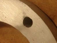
After trying to charge it a few more times, I did a discharge test, and got only @43ah from it. Interestingly, the cell popped back up to 3+v the next day. I put it back on the charger and started looking for ways to parallel an identical 20ah cells with #34. I was able to drill a hole in the tab material to insert a solder-soaked wire, but I couldn't heat it up enough to melt the solder. However, inserting a screw into the hole with the wire bolted it down nicely. I resolved to put (8) 14ga wires into each tab "module", for an effective 8ga wire, and sandwich the cell between some 0.25" plywood with nylock nuts.
Then it occurred to me that my alligator clip connection might not be letting much current get through, so I plugged a voltphreaks directly into the cell. It didn't look like anything was happening but after a week of intermittent charges (only while I was home), suddenly it was charged up to 3.68v, holding charge afterwards, and tracking at the same voltage as the other cells during discharge/charge testing. THERE WAS NOTHING WRONG WITH CELL #34 :lol: I got myself spun up about nothing. As I think back, I might have done a discharge test of that cell when it was delivered, and lost track of charging it fully back up; the only problem was that the alligator clips had a contact patch inadequate for charging. I wasted a lot of time planning a booster cell I hope I'll never need, but it sure beats the alternative.
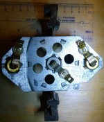
Another issue: the shifter was loose and rattly, Turns out the bushing had slipped out from between the shift shaft and its collar. I was able to unbolt the collar from the center plate and get the bushing remounted, again "without having to take everything apart - whew." Though much much better the shift shaft is still clunky, I might be able to tweak it a little better, but maybe I need to re-engineer it.

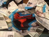
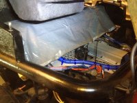
 I originally intended to duct tape this across the back of the battery box too, but I opted to make the tarp long enough that it would cover the contactors/fuses/battery terminals too.
.
View attachment 2


I put together a procedure that details everything that I need to do to be able to lift the body to service the battery or controller. It was a long and difficult process to take it off the first time, so throughout this project I overbuilt things assuming that I might never be able to get to them again. Now that I know (a) how everything comes apart and (b) what things can stay on and still fit the body, I am pleased to see it is much simpler than I feared - an afternoon project, maybe an hour or two with practice.
PROCEDURE TO LIFT BODY FOR FULL ACCESS:
=========================================================================
Remove nosecone side support bolts to clear body during lift
.....Nosecone has otherwise cleared in the past
Unbolt master cylinder at front of pedal box, 2 bolts
Feed charger wires through hole in trunk to add clearance when lifted
Remove rear fender
..... 4 bolts through rear fender and "trunk"
..... ..... Bolt, washer, washer, lock washer, nut
..... Remove Bolt through support arm on each fender scoop, and loosen support arms
..... I stored rear fender on its side before
2 Screws, 1 through each seatbelt into side of body and frame
Unbolt seatbelts from roll bar, large nut each side
remove roll bar
..... 4 bolts withwashers underneath
..... pull and disconnect brake light wire at anderson
Loosen Parking brake wires from underneath
..... Three clamps on each side, leave hanging but completely free wire for slack
..... ..... smaller center first
..... ..... larger outsides second
Loosen Bolt through tail end of shift shaft from underneath
Remove stickshift, 2 bolts, spring and floating plate
..... Lifts straight up, notice pin on shift ball pointing forwards
Slide shift shaft forward to clear battery box during lift
Edge up one rear corner of body (passenger?) to clear taillight brace
A tug should be able to lift clear of rollbar bolts and other taillight brace
Brace a 16" 4x4 bottom from front of trunk to center of back frame rear
========================================================================
CURRENT REPORT - THE BAD NEWS:
I babied it on the test drive that first night, I was exhausted and since it was a new build I was too worried about bits falling off or catching fire to push it. I noticed the throttle seemed less twitchy than I expected, the speedo and odometer weren't working, and the CA was only registering 16amps.
The next day, I went out again for a real-world range test, pushing it as hard as I could. This showed it had a power issue, the tow'd was VERY slow off the line. The peak voltage drop was @2v over 42 cells, or only .05v/cell, which told me not many amps were flowing, maybe 16a was correct! Back to the drawing board...
-I thought maybe I wired up the motor temp controller wrong, and it was telling the controller to run in limp mode because the motor was overheating, so I unplugged the cable and turned off motor temp sensing in the Kelly setup program. No Joy.
- I noticed it seemed oddly spunky in reverse, and I thought maybe the reverse relay on the tranny was opposite of what the controller was expecting, so I unplugged the reverse cables and turned off reverse speed reduction in the setup program. No Joy.
- I thought maybe there was a problem with the pot in the throttle, so I adjusted the controller to map the throttle from 10%-60% of pedal press from the 20%-80% setting it already had. I didn't see any difference in behavior, and although this was still my lead case I decided to try a few other things before tearing out wires to monitor voltages.
- I have always run the controller in 'balanced' mode, but I tried torque and speed modes, and randomly tweaked a few settings like throttle delay , just in case the was some bug with having the extreme of zero delay or something. Nothing helped, and I was out of time, so I resolved to tear out/monitor the throttle at my next opportunity.
Figuring this was just a tuning issue, I didn't worry about it, I was too busy enjoying the newfound luxury of free time, and knocking out some of the honey-do's that built up during the project. A few nights later, as I was drifting off to sleep, the detail popped into my head of how much current had gone back into the battery during recharge. This made me realize that I had entered the rshunt value into the CA incorrectly; .8333 instead of .0833 (50mv shunt / 600a = .0833). I double-checked this with our CA guru teklektik (thanks for the consult, tek!) so I know I have it correct now.
Clearly I was not going to be able to get back to sleep at this point, so I got up, programmed the CA with the correct rshunt and did a new middle-of-the-night test drive. This time numbers made sense, but in a bad way. At launch, battery side amps are only in the teens, less than 3kw, making it very slow off the line. Amps eventually increased with RPMs, but I was unable to get it to pull more than a measly 88a, far short of the controller's rating. Because it was struggling to accelerate the entire time, it drew 100wh in maybe 1/10 mile, half of what I hope to get for a whole mile. The only good news is the low voltage drop at 88a meant that I did in fact build a low resistance battery circuit.
I knew the controller's 500a rating was motor side and inflated, but I expected the controller would at worst pull its 250a continuous rating, not 1/3 of that. When it was in the bus it had pulled 250a many times, but I (much) later found out the rshunt value had been wrong, and I had not updated my expectations. This means the bus was NOT consuming 1500wh/m, that a true 500a controller WOULD have made it powerful, and I could have enjoyed it a lot more. Sigh.
Oddly, the bus felt faster off the line, despite weighing 3x as much - perhaps because it's first gear was not as steep (especially with the tow'd's big rear tires), so RPMs came up more quickly, and amps seem corrolated to RPM. The tow'd did seem to be getting lively just when it got to 88a so it could have a decent top end, but it was so slow in the beginning that I ran out of road before I could change gears. It was really slow on the hill I tried (and it made the controller HOT) so I am avoiding hills, which complicates things. I live in a very hilly area with many stop signs and streetlights so with this level of performance I can't get to a long flat road to test on, nor can I take it to get weighed.
Now that I knew what to look for, google showed a number of folks who had the same problem with the 144v versions of the KDHB model, and who had been through the missing J1/RS-232 wire problem I experienced, and like me had been successful with other Kelly's including the 72v and 120v versions of the same KDHB platform. I suspect that the 144v version took the KDHB platform beyond its practical limits, a problem resolved by clamping down amps to uselessness, especially at launch. Boo.
I have been a longtime booster of Kelly products. However, between this problem, another fiasco with their BMC V3 controller, and longstanding angst with the deceptive way they rate their controllers, it will be really hard for me to recommend Kelly controllers to anyone again despite successes I have had with them on other builds.
I was so thrilled to have the project behind me, so happy spending a few days not worrying/thinking about it at all after 15 grueling months, that this is really hard, a kick in the stomach.

OTOH, I now have a proven lightweight, servicable platform for testing motors and controllers.
I'll go ahead and install that ZILLA 2K/2000a controller I bought last summer (documented earlier in this thread); I'll have to test it to see if it actually works, it was so cheap that I have my concerns. The zilla weighs much more, is too big for the space where the Kelly is, and I'd have to redo a lot of wiring, and design/install the liquid cooling infrastructure it requires, but 2000a would be interesting. If the zilla does not work, then maybe I'll just jump to the HPEVS AC35x2 and dual controllers instead.
"Just when I thought I was out... they pull me back in!" :lol:
-JD
P{lease ignore this duplicate picture: