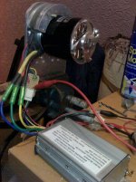
120% speed advanced timing on the controller programming

Thanks Methods. There is so much really useful stuff in posts on here that it's easy to miss, but I guess there was no good reason for me not looking in the obvious place first..............

Overall, I'm happy with the 110% setting, as it gives about 95% power at full throttle without any glitching, which is OK for what I need. My guess is that this will be very motor/controller combination sensitive, so most may just want to stay at the 100% setting and put up with the small loss in top end power.

Jeremy
 
Methods / Jeremy,

Do you think there is any risk to the controller by increasing the throttle above 100 percent? Or do you think it may even cause the FETs to run cooler as there will be less chopping?

I just finished building my 18 FET 116 controller, I haven't even programmed it yet so I'm assuming it's on 100% at the moment, but even with the standard shunt with 72V on a 10 inch wheel the torque is awesome :) So much better than that 12 fet I had before.

Mike.
 
Mike,

I suspect that there's no real useful gain in going over about 110%, plus there's a risk that the FETs might actually see a higher dissipation once the controller glitches. In my case, the motor no-load current suddenly jumps by about 25% when the glitching starts, which indicates a pretty significant decrease in efficiency. That power has to go somewhere, as it doesn't seem to increase the motor speed by much. That means it's either being dissipated in the controller or the motor (or a bit of both).

Jeremy
 
I second on that, I had the SAME EXACT PROBLEM with seting over 100%.. wierd sound and just 1-2% faster at no load... the motor seems to receive noise when seting over 100%.. the power seems the same.. i'll capture that tonight.. and will put a scope on that as well. Why this controller can't give us 100% throttle??? that's strange desing!.. it must be a reason!

It would be interesting to see if other controller have the same problem.. ex the old analog controller vs these new digital controllers...

I WANT 100% THROTTLE!..

and finally why can't we play with timing advance?.. it would be nice!

I agree with methods.. testing the trapezoidal winding vs the streight winding of the 9C would be interesting to test with over 100% throttle seting to see the difference..

Doc
 
Tonight i'm playing with the controlelr and scope.

I tried to flash it with the edited program that allow up to 200% throttle.. the one that people generally try at 150%.

and.. I get : TRANSMIT FAIL.. at around 90% of the status bar... :?

I selected the correct 818 controlelr version.. but i still dont understand why i get that fail..

anyone experienced that?

Doc
 
Doctorbass said:
I tried to flash it with the edited program that allow up to 200% throttle.. the one that people generally try at 150%.
and.. I get : TRANSMIT FAIL.. at around 90% of the status bar... :?
:lol:
I think the guys who designed these controllers didn't have you in mind, Doc! It's probably the firmware that is not made to take such a high speed setting value, and so it returns an error to the computer.

Just be happy that it didn't just take your 200%, then turn your bike into a ball of fire as soon as you touched the throttle the first time! :mrgreen:
 
ZapPat said:
Just be happy that it didn't just take your 200%, then turn your bike into a ball of fire as soon as you touched the throttle the first time! :mrgreen:


Yes ZapPat, I had that in mind.

I also tried at 99% speed and it did not worked.

My throttle is not properly configured about 0-5V band.. When i increase around 95% speed and still keep slowly turning the throttle, it suddenly jump to 100% speed... and the PWM on the scope seems to completly change and become more continuous.

Also, with the normal flash program designer, if i set it to 120% on position 3 and 100% on position 2, the 120% seems to kame less noise on the motor than at 100%... and .. the 120% is 2-3% faster... with less noise... :shock: :? :?: .. the opposite of Jeremy Harris ...

I wonder if he is using the 18 fets controller ?
 
Hi Doc,

I'm using the old, slow start, 6 FET Infineon, the one with the XC846 chip. I suspect that this glitching is a bit random when the controllers are set to anything over 100%, it's probably going to be dependent on component tolerances, motor characteristics etc. I'm using this on a relatively low inertia RC motor, fitted with Hall sensors at 120 degrees, so that may also make my controller behave differently.

What is odd is that when I run this motor on an ordinary RC ESC the phase waveform stays very clean and the motor goes to full speed with no problem. At full speed on the RC ESC there is no sign of any glitching or PWM on the phase waveform, it's just a clean trapezoidal shape.

Jeremy
 
Jeremy Harris said:
Hi Doc,

I'm using the old, slow start, 6 FET Infineon, the one with the XC846 chip. I suspect that this glitching is a bit random when the controllers are set to anything over 100%, it's probably going to be dependent on component tolerances, motor characteristics etc. I'm using this on a relatively low inertia RC motor, fitted with Hall sensors at 120 degrees, so that may also make my controller behave differently.

What is odd is that when I run this motor on an ordinary RC ESC the phase waveform stays very clean and the motor goes to full speed with no problem. At full speed on the RC ESC there is no sign of any glitching or PWM on the phase waveform, it's just a clean trapezoidal shape.

Jeremy

On MY infineon, there is alot of noise and glitch until i reach the 100%.. then it become clean :?:

Doc
 
You guys are running totally different micro controllers with (presumably) different internal firmware.
Different manufactures - different DCO (clock speed) - different instruction set

I would be amazed if the slow start controller exhibits the same behavior as the 116
They should be different once you get into the quirky zone.

-methods


EDIT: That is a nice scope. They dont specify the maximum voltage input - what is it? I think I need a scope with at least 2 channels though... Ideally 4ch
 
Good to know. Has any one put together a info section on the infineon instant start bords? I found a little in the technical section and I should be able to get mine ripping well with what I have found and methods (now 42 page long) thread. This is sweet stuff everyone keep up the great work.
 
I have secured a new shipment of 116 boards and I will be starting a new, cleaner thread.

These are assembled by Crystalyte and will be modified by me. 100V 100A 18 fet Programmable Controllers.
I will be selling completed controllers but documenting every moment of the modifications so that those who wish can DIY.
I will secure the first few pages to document everything I have learned about the 116 and we will try to keep the chit-chat down :D

Keep your eye on the Technical section. I expect shipment in about 2 weeks.

-methods
 
Doctorbass said:
On MY infineon, there is alot of noise and glitch until i reach the 100%.. then it become clean :?:
That sounds pretty normal, Doc - it's the PWM switching bellow 100% that makes that noise. If you get a trapezoid with only a couple switching spikes when at full throttle, this is good.
 
methods said:
EDIT: That is a nice scope. They dont specify the maximum voltage input - what is it? I think I need a scope with at least 2 channels though... Ideally 4ch
It is just a one channel and I would love a two or more channel espicialy when I get going with ion sensing ignition. As for the volts It goes pretty high I can remember the spec but I have mesured 160 peak to peak with the normal scale then it has a 10x switch on the probe so 1600? peak to peak I am sure it says on the websight. That company seams to have a few good scopes I like mine because of price and size.
EDIT: I found the speck sheet it is linked on that page I linked looks like 600vdc is the max rating. here it is http://www.vellemanusa.com/downloads/0/user/oscilloscopes_cross_reference_uk_rev1.pdf also compares their other scopes.
 
Just a quick heads up,,, I now can get full voltage to the motor ( no PWM ) at WOT with my un-modded baby 6 fet and no software mods this was due to the timing being slightly off..
 
Now you know you need to expand on that.... :?

Are you saying that you moved your hall sensors around?
You have sparked my interest.

-methods
 
methods said:
Now you know you need to expand on that.... :?

Are you saying that you moved your hall sensors around?
You have sparked my interest.

-methods

I will expand on it, when I have my head round what is going on, I need to do some more testing. But yes it appears that slightly moving the timing off makes my controller run a lot better, more startup torque ,speed topend (no PWM). but the draw back to this is more current draw than with a rc contoller. My first hall mod worked nice ( just reasonable ( better than a rc esc) startup torque ) smooth startup but lacked full speed due to wot being PWM but overall current was the same as a RC esc. It also appears not to have any delay in throttle response but not have fully test this yet on a big load. I need to put my original hall mod back on the motor to compare, I got a feeling that my new hall mod is slightly different spacing from the first ( the new one is Exactly 60degree spacing ). I only have a 2ch scope which is a bit of a bummer wish I had a 4ch it would make things so much easier to see what really is going on.

Edit:

OK just discovered that there is a small problem with my smaller outrunner ( the one I have been using for testing and hacking ) I dont know what the problem is yet. So I setup my other outrunner with the halls.
bigger_motor1.jpg

The startup torque is like a brushed motor :twisted: , very smooth operates at full Kv at wot (no pwm) and the really good part is slightly less current than using a RC esc. So the Issues I was having with the smaller motor appear to be a fault with the motor, the No pwm at wot is constant on the bigger motor no matter what the timing is set to.
 
don't understand.but I'm jumping in because the local university has a whole room full of scopes@$5 you pick.I'll try to get specs etc and if the type anyone is looking for :$5+ship
 
gilnet said:
don't understand.but I'm jumping in because the local university has a whole room full of scopes@$5 you pick.I'll try to get specs etc and if the type anyone is looking for :$5+ship
Tell me more. how many channels? are they the old scary hospital type big tv screen things?
 
The only differences ( that I can think of ) between my prototype hall mount ( that didnt give me full speed at wot ) and the one im using now is the lead length from the halls ( much longer on the prototype) and maybe i was using my other throttle. I will try and set the prototype back up and compare the 2 to see if this throws any light on the problem
 
gwhy! said:
The only differences ( that I can think of ) between my prototype hall mount ( that didnt give me full speed at wot ) and the one im using now is the lead length from the halls ( much longer on the prototype) and maybe i was using my other throttle. I will try and set the prototype back up and compare the 2 to see if this throws any light on the problem

Update: yes the length of the hall leads do make a difference, on my prototype hall mount the leads where about 20cm long and it was noticeable on a scope that every now and again the output at wot would sometimes be pwm, and on my new hall mount the wires are only about 8cm and the wot signals where as clean as clean as can be. Now im not sure if this is the problems that you guys are seeing but it looks like it would be worth using screened hall wires if using lead lengths greater than 16-20cm.
 
gwhy! said:
gwhy! said:
The only differences ( that I can think of ) between my prototype hall mount ( that didnt give me full speed at wot ) and the one im using now is the lead length from the halls ( much longer on the prototype) and maybe i was using my other throttle. I will try and set the prototype back up and compare the 2 to see if this throws any light on the problem

Update: yes the length of the hall leads do make a difference, on my prototype hall mount the leads where about 20cm long and it was noticeable on a scope that every now and again the output at wot would sometimes be pwm, and on my new hall mount the wires are only about 8cm and the wot signals where as clean as clean as can be. Now im not sure if this is the problems that you guys are seeing but it looks like it would be worth using screened hall wires if using lead lengths greater than 16-20cm.

I think you mean shielded? You are right, if you run the infineon hall sensor wires too far (mine are no more than 10") it can wreak havoc with the top end waveform.

Somthing I may or may not have previously posted elsewhere, but it seems to be a nice idea for this thread... Get a hex editor and modify Parameter Designer.exe to allow for higher than 120% speed advance. I have tried this at 125% and also at 150%. 125% worked for sure... about 2mph better top on the same track with the same starting voltage (actually using the previous test pack without recharging, so v would have been lower if anything) sadly if 150% works... I don't have the track length to test its top end (or maybe I just don't have a high enough current limit set).

Just somthing I thought you all would like to know... this works for the various speed settings and it works for LVC (and I am sure it will work with a few other parameters but I havent finished looking at the infineon dissassembly yet).

Hope this helps someone!

-Mike

PS: I think luke might be the only one here with enough power and track available to test this for full runout. Maybe methods. Someone who can do the testing on the road, please do = )
 
mwkeefer said:
gwhy! said:
gwhy! said:
The only differences ( that I can think of ) between my prototype hall mount ( that didnt give me full speed at wot ) and the one im using now is the lead length from the halls ( much longer on the prototype) and maybe i was using my other throttle. I will try and set the prototype back up and compare the 2 to see if this throws any light on the problem

Update: yes the length of the hall leads do make a difference, on my prototype hall mount the leads where about 20cm long and it was noticeable on a scope that every now and again the output at wot would sometimes be pwm, and on my new hall mount the wires are only about 8cm and the wot signals where as clean as clean as can be. Now im not sure if this is the problems that you guys are seeing but it looks like it would be worth using screened hall wires if using lead lengths greater than 16-20cm.

I think you mean shielded? You are right, if you run the infineon hall sensor wires too far (mine are no more than 10") it can wreak havoc with the top end waveform.
Thanks yes i do mean sheilded :oops: and thanks for the conformation.. So is the speed increase in the software achieved with auto adjusting the timing ?
 
I can confirm programmability on the 9FET, 6FET, 12 and 18 FET normal Infineon (I think the chip is infineon 846 for the MCU) which will be labeled EB8XX-??-Revision Letter(mine is EB809XC-A12). I believe the newer 116 processers have more programming ability and features but as of yet I dont' have any.

*edited - removed inaccurate technical description.

-Mike
 
Back
Top