18650 spot welding -how to- ULTIMATE REPOSITORY

If you go see my post on the previous page, https://endless-sphere.com/forums/viewtopic.php?f=14&t=68005&start=325#p1165636
I think the way I demonstrate how I would make large batteries can apply to smaller ones. By having one very short Nickel strip on each cell that connects to a sizable sheet of Copper, like 2,5mm thick, the Nickel strips being so short might stay cooler and the Copper sheet would absorb a lot of heat.
 
mistercrash said:
If you go see my post on the previous page, https://endless-sphere.com/forums/viewtopic.php?f=14&t=68005&start=325#p1165636
I think the way I demonstrate how I would make large batteries can apply to smaller ones. By having one very short Nickel strip on each cell that connects to a sizable sheet of Copper, like 2,5mm thick, the Nickel strips being so short might stay cooler and the Copper sheet would absorb a lot of heat.

Yes that would work. The reason I used wires was because my pack is not square or rectangle, almost round so I had to use wires to pass the current evenly.

If you had a simple rectangular pack, then copper bars would be better. Keep the pack flatter and no wires to get in the way. Someone on here a few pages back designed a very good pack with copper bars.
 
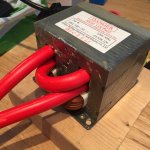
I originally had 2awg wire with 1.5 to 2 wraps and I get very minimal voltage under 1V. I could weld 15+ welds and the cable would start getting mildly hot.

They dont sell 3awg so I bought 4awg cable and I got 3.5 wraps and get 2V to 2.5V when its open. I also made the connection more secure. However now I cant go 5+ welds without the cable getting hot.

I think this is what will happen with higher guage (thinner) wire, is Volts increase, Amps decrease compared to a lower guage (thicker) wire which does the inverse.

If this doesnt help, is it even worth my while going to 6awg wire with even more wraps.
 
Solarpower said:
Does anyone know the nickel strip thickness they use on laptop battery packs? Just finished my welder, and tried to weld some excess strips from recycled cells, but that didn't stick at all!
I got some pure nickel on the way from Ali.. :)
Finally my nickel strips came in the mail today, and I got one roll of 0,1mm and a few rolls of 0,15mm strips. Sadly, I can't get the 0,15mm to stick very well... The thinner one gets welded just fine, so I guess my welder isn't that good after all? It's a 700W MOT welder, with 3AWG jumper cables and copper electrodes from Riba. For testing purposes, I just used the whole length of the jumper cables (3 meters I think), and used the clamps to hold the electrodes. Is this setup more crap than I thought? Any suggestions?
 

Attachments

  • IMG_0033.jpg
    IMG_0033.jpg
    234 KB · Views: 2,145
  • IMG_0034.jpg
    IMG_0034.jpg
    109.7 KB · Views: 2,145
1.Shorten the cable to the minimum needed and make good contact to the electrodes.
2. In my experience, those jump start cables are junk, you could get more cable in, using the welding one. (less R and heat, more current)
 
I have a Sunkko spot welder, but its only good for 0.15mm of pure Nickel.

The welder is a 220V version. Can i replace the transformer in it... with a Microwave Transformer from a 1100w, which has been moded with Thicker gauge on the secondary. which I think should be way lots more current than the stock transformer.

Anyone can comment if this will work? it will be a direct swap out and in of the Transformer... basically i want to use the pulse ( timing) and the duty cycle knob.... which give fine tuning...

But just with a BIGGER transformer. will it work ....as the Primary AC side power should not change much.. just that the secondary has more Punch or am i just dreaming.... :roll:
 
Hmmm that got me thinking, maybe my nickel strips are too thick too.
I cant remember if I bought my nickel strips from batterysupports.com or fasttech.com

I got my MOT out of a high powered microwave ~1100 or 1300W. I got 1.5 wraps in 2awg, or 3.5 wraps in 4awg.
I took out the shunts when I installed 4awg, to get the extra room. I dont really know what those shunts do.
 
Do you think this cell needs to be replaced?

I had the welding probe on another parallel group, and hit the edge with the other welding probe. The cell had a hole in the insulation already there and it melted the edge a little.

I believe you can see the plastic gasket.

The voltage is still 3.669 as it was before I did this.

Is this a must replace, or is it probably OK?

How easily do these cells get damaged when you accidentally short them under a second like this?

 
Looks ok. Did you get any smell. . Or liquid ouzzing out? If no leakage. . I take it as it's ok. Any doubt. . Toss it.
 
Chuck it!! it'll take 2mins of your life now.... Or hours when it fails later and you have to take the whole pack apart to get to it. It looks like there's a significant heat affected zone judging by the colour of the heat shrink - not good!
Was the current path through a bunch of cells? Can't imagine ~1000a is going to do any of them any good. Keep an eye on them as well. Maybe insulate your probes to the tip to help guard against accidental shorts.
 
ian84 said:
I have a Sunkko spot welder, but its only good for 0.15mm of pure Nickel.

The welder is a 220V version. Can i replace the transformer in it... with a Microwave Transformer from a 1100w, which has been moded with Thicker gauge on the secondary. which I think should be way lots more current than the stock transformer.

Anyone can comment if this will work? it will be a direct swap out and in of the Transformer... basically i want to use the pulse ( timing) and the duty cycle knob.... which give fine tuning...

But just with a BIGGER transformer. will it work ....as the Primary AC side power should not change much.. just that the secondary has more Punch or am i just dreaming.... :roll:
Any insight to this?
 
I'd pull it because if it goes bad you just lost the whole parallel group for less than 4 buck and 15 mins of your life. I would recommend never taking a chance with a "questionable" battery....ever!

Tom
 
Thanks guys, I pulled it. The reason why I was hesitant is because my pack had to be built compressed so is a little more work to replace a cell. I also had a nickel tab on one side.

However, the cell was at the edge, so that made it a lot easier.

Do you think any damage happen to any of the other cells? there are no burn marks on those. I believe why this one got burned so badly is I had the negative on parallel group 20 shorted to the negative on the first parallel group. These two parallel groups give me my 70 volts. I wonder if it had a higher voltage differential.

SOmeone said like 1000 amps by shorting cells, but I don't think that many amps can flow because the metal burned away acting as a fuse. Plus where I had the other probe pushed into another cell it didn't burn it at all. If that many amps went through I think it would have burned where I had the other probe placed.
 
OR- my bad. I was thinking it was the welding current. So not a1000amps luckily, but I'm glad you ditched it.
Ian84- I don't know much about these welders but from the insides of a dn10 that I saw they are pretty simple. I guess a bigger transformer could work it might take a bit of fiddling. I got a massive transformer out of a ups system. The output needs to be 3-8 volts or there abouts which is very uncommon in a high power transformer so you'll need to rewind it. Be sure to maximise copper fill. Use foil if you can - it isn't difficult to rewind them, just a bit time consuming. Obviously get a transformer with a higher wattage than your existing one- say 1300-5000 watts. If you use a MOT take out the shunts, they lower the power noticeably.
You might have problems with the feed circuitry blowing after the upgrade but it's worth a try I guess.
 
Nobuo said:
Cells are perfect cylinders, if you make good shapes and patterns where cells are very exactly placed, the weight will perfectly distributed if the battery have an impact for example, and is almost impossible that both insulators of two consecutive cells will be punctured making its cathodes electrically in contact.

...yet we have had several fires over the years from hot glue packs where the suspected cause is that plastic layer has chafed, or the cell got hot enough (abuse, overdischarge) for the insulator to split and an in-pack short has occurred. I have worked with round cells that were not perfect cylinders, and I have seen round cells swell in the middle. There is a reason professionally made packs use cell holders instead of hot glue, ignore it at your peril. At the very least, put some additional barrier between groups of parallel cells in series. :D

-JD
 
oatnet said:
Nobuo said:
Cells are perfect cylinders, if you make good shapes and patterns where cells are very exactly placed, the weight will perfectly distributed if the battery have an impact for example, and is almost impossible that both insulators of two consecutive cells will be punctured making its cathodes electrically in contact.

...yet we have had several fires over the years from hot glue packs where the suspected cause is that plastic layer has chafed, or the cell got hot enough (abuse, overdischarge) for the insulator to split and an in-pack short has occurred. I have worked with round cells that were not perfect cylinders, and I have seen round cells swell in the middle. There is a reason professionally made packs use cell holders instead of hot glue, ignore it at your peril. At the very least, put some additional barrier between groups of parallel cells in series. :D

-JD


i don't like using hot glue. i prefer silicone

and i use double layer kapton tape between parallel groups
 
Those cardboard cell separators look good if you haven't space for the normal rectangular cell holders. I haven't seen them before.
 
Overclocker said:
i don't like using hot glue. i prefer silicone
and i use double layer kapton tape between parallel groups

I'd point out that one is not actually gluing the cells together, but only the thin plastic wrappers around the cell, and they were never designed or intended to provide structural integrity. When a pack is held together by glue and cellophane, it is one good twist away from splitting/peeling the wrapper away from the cells and exposing a potential short.

One could argue that the nickel tabs add structural integrity - not the best choice at the positive end of the can, although the welds do have pretty good grip - but take offroader's pack (sorry to single you out man, :oops: no judgement you are just a recent example :D ) where the parallel groups are joined by loose copper wires, not stiff nickel tabs, so there is no integrity but cellophane between the series cells.

A rigid close fitting box can provide needed structural integrity, but once you have added the volume of a box, have you saved that much over cell holders? The modular cell-holders have a pretty big gap between cells, but the fixed-configuration cell holders are pretty tight...

A few layers of Kapton tape is a good direction. punx0r mentions cardboard which is a also a decent solution; a123 M1 cells used to come in cardboard sleeves, and I've used 3 layers of simple newspaper between pouch cells as a chafe layer.


This case is a sad example - while we will never prove what caused the fire, note that this pack was glued together instead of using cell holders, and read comments from other old-schoolers about what they suspect. Can you imagine this happening to your build after 200km? Read on:

CLICK HERE to read "Raptor on Fire"

.
 
Need advice here.

I accidentally forgot to weld down a single cell. I was meaning to check this but charged the pack from 3.66 to 4.00 volts. Then I decided to check all the cell tabs.

I forgot to weld down a tab and every two cells are in parallel in my pack because I am not complete. Therefore 1 cell got charged instead of 2 cells. The cell read about 4.22 volts after sitting for a couple of days.

Discharging shows normal to a bit higher than normal capacity.

I think I may be OK here. But I have a concern. Is it possible that I could have overcharged the cell to say 4.3 or 4.35, and it fell back down to 4.22 volts?

Or did I luck out and most likely only charged it to 4.22 volts and should be OK, because if I charged it higher it would probably still be higher?

I really don't want to pop this cell out because it is centered in the pack.

Warning to everyone to always double check your welds after your build. I planned on doing this but didn't.
 
Actually, I think I must have over charged it a lot because running it from 4.22 to 3.7 took about 1900 to 2000 MAH, when normally it would take 1500. I overcharged it about 400 MAH more or 12%.

Or a 3300 MAH cell to 3700 MAH. I'm now sure how bad one time doing that is. I'm considering just replacing the cell.

What is odd is that the resting voltage was only 4.22 volts for a 400MAH overcharge. I would think it would be much higher.
 
Many 18650 cells are rated for use up to 4.35V. I doubt even a 4.2V-rated cell would self-discharge from that level down to 4.22V in a couple of days. If it's good quality cell I wouldn't worry about it, but then if it's only one cell in a whole pack and swapping it is simple and gives you peace-of-mind, why not?
 
Punx0r said:
Many 18650 cells are rated for use up to 4.35V. I doubt even a 4.2V-rated cell would self-discharge from that level down to 4.22V in a couple of days. If it's good quality cell I wouldn't worry about it, but then if it's only one cell in a whole pack and swapping it is simple and gives you peace-of-mind, why not?

Another Bummer, I actually found one other cell that was not connected. The reason why I screwed up is because the way I built my pack using wires, in the beginning I was inexperienced so I didn't weld down the wires until I was sure they all fit in case there was a problem. I only welded one half of the tab so I missed it. Towards the end of the build I knew exactly the lengths so I welded down the whole tab at one.

This other cell was at 4.26 volts. I may have pushed the other tab down to discharge the other one a little.

I'm going to just leave both cells for now and see how it cycles with the other cells in the pack. I'm only going to leave two cells in parallel for some cycles to see how it is. If I see signs of it being a different voltage I'm going to replace them.
 
Hey guys I've been reading this thread and shopping online. I am in need of a spot welder. I have a stack of packs to repair with copper strips and I have plans to make more packs in the future with nickel strips. I would like to be able to do the thicker stuff and run the highest c rated cells I can. But it's a tool that will not be used a lot and I'm on a budget as I'm hoping the Anti with other equipment around the shop.

Suggestions? Seems JP is out right now...
 
Back
Top