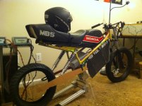
1982 MB-5 30kW peak 230 lbs Complete new VIDEO! 82mph

Dude, don't even think about paying those kinds of prices for a LED headlight. If you want to DIY, get a cheap incandescent for the housing and use one of the latest and greatest 100W LED arrays and drive it gently for very little heat. If you don't want to DIY there are much cheaper more output solutions with proper car rated water and dust resistance, IP67 rated, for much cheaper.

My guy is working some lenses with limited vertical dispersion into the equation right now, but I have some with round beams already. My favorite is the one in a sleek housing with five 3W LEDs in a straight line. Three 3W LEDs is inadequate light for a moto without driving them pretty hard, and I don't see proper heat sinking on those units. It may be fine while cruising, but get stuck in traffic and it's either doomed or isn't putting out much light.

John
 
John in CR said:
Dude, don't even think about paying those kinds of prices for a LED headlight. If you want to DIY, get a cheap incandescent for the housing and use one of the latest and greatest 100W LED arrays and drive it gently for very little heat.

That's a great solution for low cost and high output, but you won't get a motor-vehicle quality beam pattern that way. 'Round these parts, perceived failure to dip your high beams will get you pulled over faster than driving like a dick, speeding less than 10 over the limit, or talking on the phone at the wheel.
 
Chalo said:
That's a great solution for low cost and high output, but you won't get a motor-vehicle quality beam pattern that way. 'Round these parts, perceived failure to dip your high beams will get you pulled over faster than driving like a dick, speeding edit: MORE than 10 over the limit, or talking on the phone at the wheel.

true. but how do we know this 3 LED 7 incher has a better beam? there doesn't look to be a shield.. maybe I don't see it?
 
hillzofvalp said:
Chalo said:
That's a great solution for low cost and high output, but you won't get a motor-vehicle quality beam pattern that way. 'Round these parts, perceived failure to dip your high beams will get you pulled over faster than driving like a dick, speeding edit: MORE than 10 over the limit, or talking on the phone at the wheel.

true. but how do we know this 3 LED 7 incher has a better beam? there doesn't look to be a shield.. maybe I don't see it?

That fluting and waviness you can see in the LED optics is to create non-round beam shapes. Whether they did a good job of it-- or a legally certified job of it-- is an open question, but it's certain that light doesn't throw a round pattern. For what it's worth, EU-certified headlight beams are generally regarded as much better than US-certified headlight beams.

(I meant "less than 10 over", e.g. 37 in a 30mph zone. 10 or more over the limit on the radar gun will surely get you pulled over by any cop who's bothering to using a radar gun.)
 
the seller responds:

"Not blinding that I'm aware of. Not DOT-arrpoved, so song as 'for show use only'.
Very popular for project bikes etc though.
If you're not happy to buy it, I understand."


You know, I'm going to be running an auxillary pack for 12V system and micrcontroller.. most aftermarket lights are 12V. I figure if I put in a 200Wh auxillary pack that's like 4 hours run time of a halogen or HID. I can have a switch to disconnect the dc-dc from the 12V battery whenever I want to maintain all range from the main pack. Or no DC-DC and stop being a pussy
 
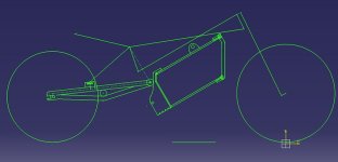
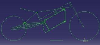
this is with the 150/70-13 (top) and 140/60-13 (bottom). Farfle is going to whip up most of the swingarm in the West and I will make the dropout inserts and have them welded here in Indiana.
 

Attachments

  • mbbike.jpg
    mbbike.jpg
    30.8 KB · Views: 1,538
  • mbbike19.2.jpg
    mbbike19.2.jpg
    30.8 KB · Views: 1,538
I like the pivot higher than the axle to help reduce squat on acceleration. The swingarms in the drawings too with at least some triangle instead of parallel tubes. It even looks like there's enough space to go mid-drive with the motor on the swingarm if you change your mind later, so make the sides of the swingarm parallel up to close to the pivot....Maybe even add a few inches of flat steel to the bottom now, so it would be super simple later. If you have parallel dropouts done now at 175mm, then you can do your own flats on the wire side axle round to fit the bike. Just take your time and make sure it doesn't get too hot while cutting them, so the wire insulation inside doesn't melt.

the only things I don't like are:
1. The clamping dropouts. I'd like to see the forces spread over a greater distance up the swingarm.
2. Shock mounts. I never did like them so far from the dropouts on a straight piece. I may be strong, but doesn't look it. How about the triangle of the swingarm on top, and put the peak of the triangle at the shock mounts. I think that could be made to look slicker, and look and be stronger.
 
If the shock pivot is at the top of a triangle (reversed as shown) then a combination of three things has to happen: the slot of the dropout has to go up, the swingarm gets shorter, and the shock mount pivot goes closer to the wheel axle. All of these things are more cosmetically challenged to me.

edit: Oh by the way, the dropouts have "plugs" that have a close fit to the inside of the tubes up the arm 1-2 inches.. Probably just on the top one.
 
hillzofvalp said:
If the shock pivot is at the top of a triangle (reversed as shown) then a combination of three things has to happen: the slot of the dropout has to go up, the swingarm gets shorter, and the shock mount pivot goes closer to the wheel axle. All of these things are more cosmetically challenged to me.

edit: Oh by the way, the dropouts have "plugs" that have a close fit to the inside of the tubes up the arm 1-2 inches.. Probably just on the top one.

It would be good for the shock mount pivot to be closer. Draw it and maybe make the triangle slightly larger too and watch what it looks like. Triangle could go on the bottom too, but either top or bottom it will look more "right" and will be stronger and more rigid with the shock mount and triangle of the swingarm in the same location. Having them apart is like having a vertical support tower on a bridge between pilings under the bridge instead of in line with a piling.
GG.JPG
 
I agree it would be ideal. However, I would need shorter shocks to do that... which I could look into. Also, if I do move it towards the shock mount, I won't be able to accept a 150/70 tire if I choose to down the road (that's leaving .35" clearance with big tire.. 1.25" clearance with smaller tire).

This is using .059" 1" 4130 steel. This swingarm is longer than the orginal, but it is probably going to be a few orders of magnitude stronger. Let's also keep in mind I'm not jumping the bike, it weighs under 200 lbs, and I'm shifting a lot of the weight to the front of the bike by extending it to around 1378mm from 1215mm.
 
If you're building a new swingarm, especially since it's longer, then you should be going monoshock anyway. Gotta have an open mind no matter how tired you are. You should know me enough by now that I'm not going to sugar coat anything unless someone is sick. Pats on the back are for when you're up and blasting around.

Ask Farfle to see his video of swingarm flex on the swingarm of his bike before you go making claims about orders of magnitude stronger or more rigid. Moto stuff has thick heavy tubing, so surpassing it is likely to require structure.
 
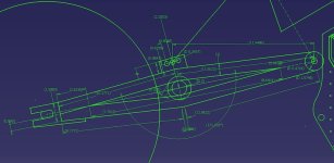
k. If I go down to 11" shocks from 13" and I make the swingarm symmetric with two " triangles", then I can also hide the pivot points on the 2" middle tube. However, I will have to widen the arm an 7/8" on each side, but that could allow me to weld the dropouts on the inside wall. Get it?

edit: mono shocks are an option but doesn't looks as retro. Also probably more $ to set up and more time getting it figured out and welded
 
this is as good as it would get with the 13" shocks that I have. Or I can get my hands on aftermarket or orginal 12" or even 11" guys and put the pivot at the top. I almost rather leave the space above the battery open at least for the initial build. I don't have everything all mocked up yet to know if the monoshock would get in the way

mb5symmetric.jpg
 
this is with an 11" shock pair. It will still be compatible with mono shock with few mods in the future. I want to get this thing rolling asap so I'm not changing too many things.


John, in this one, the dropout plugs into the top tube and it welded around the top tube. Also the lower support extension of the dropout goes beneath the lower tube and is welded on 2-3" long on each side. I was originally going to do more of a vertical style dropout, but I rather have more alignment and wheelbase flexibility. To put on the bigger tire, I will have to slide the axle an inch or so further (to clear the center tube). I may put dual pinch bolts.. one for each setting (maybe one is more appropriate). honestly though if I ever put on the bigger tire it would be so much easier to just compensate for height in the rear by lowering the front at the triple tree.

Thought of doing removeable dropouts, but I think what's going to end up happening is I'm going to mill the flats on the motor parallel first.. one will have to be a tad smaller than the other, but that's not really a problem.

The plug on each dropout will make it easy to jig up with the motor bolted in. It will at least let me see the sizing issues and allow me to know how much material to face off the dropout to get spacing correct.This will probably be done in the lab next to a mill with a few trial and errors.
 

Attachments

  • standardarm.jpg
    standardarm.jpg
    47.7 KB · Views: 1,492
Looking good, and since the motor is only about 8" in diameter without the spoke flange, you've got room to go mid-drive at some point. Are you sure there's room for the tire?
 
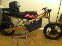
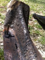
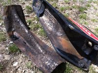
Getting close, dudez! I got a tank on ebay for $100.. major rust inside, but not very much rust on paint. I've gutted it out today with a dremel grinding wheel for a solid half hour. I also drilled out the tank steel underneath the seat to lighten it up some.

A lot has to happen in the next 6 weeks for this to come together by summer:

motor needs to arrive
Farfle's replacement swingarm needs to arrive
I need to make special dropouts and have them welded locally
need to waterjet CF battery panels and 7075 reinforcements for front CF brace (insurance policy/ CF needs a large washer anyways)
need a set of 11" shocks
a billion other things need to fabricated and installed (controller mounting plates.. DC DC.. arduino programming..charger..)
Charger needs to be installed (low priority obviously cause I have hyperions setup for 28S). I have no idea the best way to go about testing the 220V charger. The bms will trigger a solid state AC relay which will have a 15A breaker in it. I suppose I could try it first at the charging stations if I'm careful.

Realistically I'll have the frame without swingarm powdered matte black within 3 weeks and tank and CF side panels sprayed at body shop (green?). I measured the MB5 logo font and reproduced it on the CF side panel. The future goal is to animate these cut outs as dual purpose visibility and turn signal indicators (similar in behavior to the current mustang turn signal pattern). That's way down the road.

I'm going to try to get all the electronics mounted in the mean time so I can deal with the motor last and be done. Looking at 220V 3kW 4x4x6" charger and J1772 resistor "hack". I want the J1772 port to be hidden under the top glove cap (void frontal tank area in pictures).

I'm pretty happy with how it's turning out. Feels nice to finally check some stuff off the list. I'm looking to hear ES's opinions on aesthetics (constructive criticism please). How would you paint it? Would you say 93V, 93VOLT, or 93VOLTS? Or neither? I thought Volts would be more understandable to general public than say 25KILOWATTS. Plus, I might be running more than 25kW someday maybe with a different motor...
 

Attachments

  • IMG_3876.jpg
    IMG_3876.jpg
    86.5 KB · Views: 1,375
  • IMG_3877.jpg
    IMG_3877.jpg
    82 KB · Views: 1,375
  • IMG_3879.jpg
    IMG_3879.jpg
    73.3 KB · Views: 1,375
  • IMG_3880.jpg
    IMG_3880.jpg
    89.8 KB · Views: 1,375
  • IMG_3871.jpg
    IMG_3871.jpg
    267.9 KB · Views: 1,375
  • IMG_3873.jpg
    IMG_3873.jpg
    161.7 KB · Views: 1,375
John in CR said:
I like the pivot higher than the axle to help reduce squat on acceleration.

Just a quick question: If the bike is running a hub ( no chain to pull the wheel up ) then how can the bike squat on acceleration :?:
 
I've always liked candy green with silver... I would put 93V, as it refers a bit to 16V or 32V you sometimes see on cars. But i would also think about putting 1.21GW, the movie reference will put a smile on peoples faces...
 
I think the 93Volt is perfect. I love the font, it works well with the bike. Unless you're going to work "giggawatts" in somehow, I'd say leave it;)
 
Lebowski said:
I've always liked candy green with silver... I would put 93V, as it refers a bit to 16V or 32V you sometimes see on cars. But i would also think about putting 1.21GW, the movie reference will put a smile on peoples faces...

Should I spell out volts or do just V? I like the 1.21GW idea
 
gwhy! said:
John in CR said:
I like the pivot higher than the axle to help reduce squat on acceleration.

Just a quick question: If the bike is running a hub ( no chain to pull the wheel up ) then how can the bike squat on acceleration :?:

As you launch the inertia primarily of the rider puts force to compress the suspension. Mine squats quite a lot, and the pivot is down very close to the BB. I could be wrong, but I believe a higher pivot point will reduce the effect because it reduces the length of the lever and the force to move will be applied to the frame from a lower relative position.
 
Back
Top