methods
1 GW
1KW On board Charging station
EDIT: Now charging 12S and 24S Lipo at 13A CC
100.8V output at 11.5A
6' charging cable
24V cooling fan
45A Anderson charging connector
Can also charge my wife's 50V pack while we are out on the road.
I have a 24S 10Ah Lipo pack and she has a 12S 10Ah lipo pack
I could charge a 50V pack at 20A but I configured it for 10A
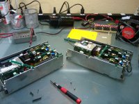
To build this charger I started with two modular power supplies
I disassembled the supplies and swapped the modules around
The final arrangement is as follows:
18V@6A
18V@10A
28V@15A
18V@6A
18V@10A

Before I had to use two supplies to hit 100V and that was too bulky
The module I eliminated was a 5V@20A
View attachment 1KW_100V_11.5A_Onboard_Charger_002.jpg
The dimensions are 5" wide by 9" long by 3.5" tall
weight is 3lbs 14oz with 6' power cable
It draws 11A from the outlet in CC mode so it is safe for 15A circuits
I am in the middle of rebuilding Project Mayhem again so I am not sure exactly where I am going to mount it
Probably hanging off the ass-end so I can drag the electrical cord like you see in the EV pictures :wink:
The supply is totally protected
Balancing is done with my super secret BMS that I will be unveiling soon
It consists of COTS (commercial off the shelf) equipment that has been hacked
Featuring an adjustable LVC that activates the brake if ANY cell hits LVC
1A Balancing done with a micro controller
Disconnects charger if cells go over HVC
Size is tiny, price is comparable to the 24ch BMS built here
Modifications are de-soldering 1 to 4 resistors (optional)
Tapping 2 to 5 lines into a circuit board
Attaching up to the brake line
All parts freely available on ebay
I am excited. . . Need to test more before opening my big trap though!
Hate being embarrassed when things blow up.
-methods
EDIT: Now charging 12S and 24S Lipo at 13A CC
100.8V output at 11.5A
6' charging cable
24V cooling fan
45A Anderson charging connector
Can also charge my wife's 50V pack while we are out on the road.
I have a 24S 10Ah Lipo pack and she has a 12S 10Ah lipo pack
I could charge a 50V pack at 20A but I configured it for 10A
To build this charger I started with two modular power supplies
I disassembled the supplies and swapped the modules around
The final arrangement is as follows:
18V@6A
18V@10A
28V@15A
18V@6A
18V@10A

Before I had to use two supplies to hit 100V and that was too bulky
The module I eliminated was a 5V@20A
View attachment 1KW_100V_11.5A_Onboard_Charger_002.jpg
The dimensions are 5" wide by 9" long by 3.5" tall
weight is 3lbs 14oz with 6' power cable
It draws 11A from the outlet in CC mode so it is safe for 15A circuits
I am in the middle of rebuilding Project Mayhem again so I am not sure exactly where I am going to mount it
Probably hanging off the ass-end so I can drag the electrical cord like you see in the EV pictures :wink:
The supply is totally protected
Balancing is done with my super secret BMS that I will be unveiling soon
It consists of COTS (commercial off the shelf) equipment that has been hacked
Featuring an adjustable LVC that activates the brake if ANY cell hits LVC
1A Balancing done with a micro controller
Disconnects charger if cells go over HVC
Size is tiny, price is comparable to the 24ch BMS built here
Modifications are de-soldering 1 to 4 resistors (optional)
Tapping 2 to 5 lines into a circuit board
Attaching up to the brake line
All parts freely available on ebay
I am excited. . . Need to test more before opening my big trap though!
Hate being embarrassed when things blow up.
-methods


