1KW On board Charging station

methods

1 GW
Joined
Aug 8, 2008
Messages
5,621
Location
Santa Cruz CA
1KW On board Charging station

EDIT: Now charging 12S and 24S Lipo at 13A CC

100.8V output at 11.5A
6' charging cable
24V cooling fan
45A Anderson charging connector

Can also charge my wife's 50V pack while we are out on the road.
I have a 24S 10Ah Lipo pack and she has a 12S 10Ah lipo pack
I could charge a 50V pack at 20A but I configured it for 10A

To build this charger I started with two modular power supplies
I disassembled the supplies and swapped the modules around
The final arrangement is as follows:

18V@6A
18V@10A
28V@15A
18V@6A
18V@10A
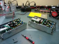
1KW_100V_11.5A_Onboard_Charger_001.jpg

Before I had to use two supplies to hit 100V and that was too bulky
The module I eliminated was a 5V@20A

View attachment 1KW_100V_11.5A_Onboard_Charger_002.jpg

The dimensions are 5" wide by 9" long by 3.5" tall
weight is 3lbs 14oz with 6' power cable
It draws 11A from the outlet in CC mode so it is safe for 15A circuits


I am in the middle of rebuilding Project Mayhem again so I am not sure exactly where I am going to mount it
Probably hanging off the ass-end so I can drag the electrical cord like you see in the EV pictures :wink:

The supply is totally protected
Balancing is done with my super secret BMS that I will be unveiling soon
It consists of COTS (commercial off the shelf) equipment that has been hacked
Featuring an adjustable LVC that activates the brake if ANY cell hits LVC
1A Balancing done with a micro controller
Disconnects charger if cells go over HVC
Size is tiny, price is comparable to the 24ch BMS built here
Modifications are de-soldering 1 to 4 resistors (optional)
Tapping 2 to 5 lines into a circuit board
Attaching up to the brake line
All parts freely available on ebay
I am excited. . . Need to test more before opening my big trap though!
Hate being embarrassed when things blow up.

-methods
 
Absolutely fantastic work!

If you want another beta-tester for your BMS, I''m more than willing.

Great Job Methods!


-Luke
 
Looks perfect for , er, borrowing a charge! Yer looking at what, 30 -60 minite recharge? Be real nice for a long ride, a nice lunch and a long ride home. You guys that build stuff blow me away! :shock: Brilliant!
 
The idea is that the wife and I are going to start taking rides to San Francisco

We ride the bikes from Livermore to Dublin and steal a charge
We then board BART (Bay Area Rapid Transit) and take it to down town San Francisco
We can then ride all day and steal power whenever we see it
The cool thing about fast chargers is even 12 minutes worth of CC is 200Wh of energy
Thats 100wh each, at 20wh/mile we can go 5 more miles without pedaling
If we pedal that is 10wh/mile so we can go another 10 miles each

Then we take BART home and ride the rest of the way

I also have a 12V switcher on my bike so I have a cigarette lighter.
From the cig. lighter I can:

* charge cell phones
* Plug in a cheap small 70W inverter to get 110V AC
* Charge batteries for flashlights
* Make sparks for fire

-methods
 
Awesome Methods! Is there going to be an online tutorial, or I can I just send you some money for one? :p

Also,I read that your wife is a laser physicist... If this is true, I was wondering if she would be willing to design a laser anti-infringement system. It would work by shooting a visible beam onto the road or into the air. The reason I was thinking about this, is that one of these days I want to build a groundhugger, and the thought of being that low in Socal with all the jacked up bro rides, I would want a system better than just a tall flag (actually to do away with the flag, uber dorkside). One of my friends used to have a pocket laser pointer that was customized to shoot out a powerful green beam that was visible to the point that you might think the FEDS could show up anytime. Just a thought.
 
Unfortunately my wife works with high dollar lasers. . . As in the largest laser in the world.
She finds anything that is measured in watts (let alone mW) boring so I doubt that will happen.
Think KW, MW, and GW

I am just going to put a tutorial up as I have absolutely no interest in business ;)
I probably should not have said anything till I was done. . . I am getting IM's form people as well.
I dont want to start sounding like DeafScooter with my "Secret Blueprints"

This BMS is nothing more than the following:

For LVC protection Only: $18 per each set of 6 channels
COTS low cost LVC Lithium Monitor system that plays an audible tone
Adjustable LVC
Tap into the buzzer output and tie that into your brake line with a diode & maybe a BJT and you have an instant LVC protection system with a variable LVC that will trigger on any cell
No limit to the number of cells
Very, Very small
Digital reading of every cell voltage
Programmable
Audio alerts
Highly accurate

Now, for full protection:
Low Voltage protection + High Voltage Protection + Balance (Balance at 250ma, 300mah, and 1A)

Fixed LVC: $25 for every 5 channels, no digital readout, low balance current
Variable LVC: $25 for every 4 channels, digital readout, 1A balance current

All I am doing is taking a COTS balancing board, overlapping channel A6 with B1 and B6 with C1 etc.
Removing all of the B1, C1, ... shunt resistors
Tieing all of the "buzzer outputs" together with a diode and some BJT's
Charging through a Fet. that kicks off if anything goes wrong

For this system you need to have your power supply or charger set to the EXACT voltage of your system
It will not allow sloppy voltage like the 24Cell BMS will.

Let me shut up about it till I have a working prototype with instructions, pictures, and test data.
All I need is for someone to try it out first, screw something up, waste money, puff batteries, and then state that it is a bad idea.
I will work the kinks out.

For the average 16ch pack it should cost around $100 for the full blown version

-methods
 
Ok, I am getting blown up so I will build the prototype this weekend

I only have enough to make a prototype for an 11S system but it scales
Trouble is that I still have to reverse engineer the chip to figure out how to control the standby current and reset the system in the case of hitting LVC

This will have a fixed LVC of 3.0V on any cell
Balance current of 250mA
HVC Cutout of 4.25V

This will pump your brakes if there is a delta of 200mV between any two cells
This will lock your brakes if any cell drops below 3.0V

This is just the module that I happen to have in hand. I have two of them and they are 6S each.
They are $25 per 5 channels

-methods
 
Wow, cool power supply hack, Methods!

Something I can't figure out though is how you get 11.5A out of five series connected modules rated each at 6A, 10A, 15A, 6A and 10A? Wouldn't the output be limited to the lowest module's current rating, meaning 6A?

I'm looking forward to seeing your BMS creation, but I'll be patient and not PM you! Just one question though: Will the per-cell high voltage cutoff signal be available to the controller, in the same way that the per-cell LVC is? Something like and OR'd pull-down on the first cell hiting 4.25V or so? If you wonder why I ask, it is for a more robust regen setup, to protect the first full-charged cell from beeing fried from over-voltage, the same reasons a BMS does this during regular charging. Not as likely to happen as a per-cell LVC event of course, but it only takes one overcharge of a cell to start damaging it, making further damage to it more likely afterwards as it is now in a weakened state compared to the other cells.

BTW, are all "lambda" power supplies modular like this one, or only certain models?

Pat
 
ZapPat said:
Something I can't figure out though is how you get 11.5A out of five series connected modules rated each at 6A, 10A, 15A, 6A and 10A? Wouldn't the output be limited to the lowest module's current rating, meaning 6A?

For some reason I always get the impression that you are challenging me. :?
I am probably just sensitive. :lol:
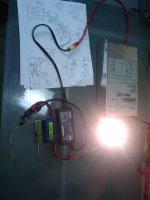
I set up a test just for you. Here is the charger driving two house heaters at 11.44A in CC mode

1KW_Charger_002.jpg

If you did a superposition on the circuit it would make sense
At 100.8V yes, your limit would be theoretically 6A
In reality it can push more like 7.5A because there is some margin built into each supply
But what happens if you load it down into CC mode?
Lets say you have a 90V 10A module and a 10V 5A module
If you load the circuit down to 90V then the 10V 5A module goes to constant current
The 90V module is still doing constant voltage and drives the current right through the 10V module
If you load it down to 80V you will get 80V@10A (really 11.5A with margin) and it will push right through the 6A module

So in CV mode you are correct, current is limited to the smallest
In CC mode you get the highest rated current

SO then you ask: How come it is not 15A?

36V@6A - This section is loaded down to CC and considered a short circuit
36V@10A - 36V+28V = 64V, so any CC mode above 64V will give you 10A. 10A + margin = 11.4A
28V@15A

So I am loading the supply down to something like 75 or 80V. That is where the 11.4A comes from, the Max current of the 10A supply
The 6A circuit is already running full out CC.
The 15A circuit is still running CV

Make sense now?

ZapPat said:
Just one question though: Will the per-cell high voltage cutoff signal be available to the controller, in the same way that the per-cell LVC is?

Yes, if any one cell goes below 3.0V or above 4.22 or 4.25V then it will activate an optocoupler that will hit the brakes
The problem now is that there is an additional function that "pumps" the brakes if any cell deviates more than 200mV from any other cell. This could be a problem and I am trying to figure out how defeat it.

ZapPat said:
BTW, are all "lambda" power supplies modular like this one, or only certain models?

I dont know. These are just the supplies that I get for free. I have about 6 now.

-methods
 
So it is already Sunday morning and this is what I wanted to be doing:

PLAYING WITH MY TOYS!!!
What_I_Wanted_To_Do_This_Weekend_001.jpg

Here is my new 1KW supply driving a Toshiba notebook brick
The brick is rated at 15V 4A
Here I am running it at 15V 5.5A
I burned it in for over an hour

The Toshiba is such a good supply that when you first load it down it turns off, then slowly sneaks the current up till it is running full CV. Totally protects itself from short circuit but then auto recovers.

Here is what my wife had to say about that:

Bap Bap Bap.jpg

So I told her!

Playing with my ebike.jpg


I did get a small amount of progress made but she was always popping her big fat head up!

Tanai Schematic.jpg


I got an order placed for 4 of the main modules that I need to build the super-simple adjustable LVC only board
They will be here in less than a week
For the 1A balancing modules I will have to wait. Nobody on earth has them and the one guy who can get them tells me that I have to wait until after Chinese New Year.

I came up with a design that uses 1 opto coupler and one resistor for each set of 6 cells
The resistor may or may not be necessary
The plan is to de-solder the buzzer, bend the leads on the opto, and solder it right onto the COTS board
I may be able to use the 8pin dual opto's and run the two inputs in series to avoid the resistor. Depends on how much voltage is driving the buzzer. Could possibly tap into the cots circuit at a different place too.

I want to keep it as Ghetto simple as possible. No additional boards or layouts or fancyness
Just a COTS part with a couple more wires hanging out of it.

-methods
 
Christ!

This is what I got from Ebay just now:

"Dear Patrick, Thanks for your order. I just inform you that the item will ship on next Thursday because our country is starting the Chinese New Year holiday so that our post office were off until 28/01/2008. The tracking number will inform you again once the item dispatched. I'm sorry for the happen may inconvenience to you cause.
Best Regards"


I just talked to homeboy yesterday and he said that anything he has in stock will ship ASAP
(as opposed to the 1A modules)

I guess it was a play on words. . . sure HE shipped it out ASAP but he neglected to tell me that the flipping post office is having the worlds longest siesta.

-methods
 
methods said:
For some reason I always get the impression that you are challenging me. :?
I am probably just sensitive. :lol:
I'm just trying to understand since I see it differently, but don't have your supply here to see for myself, and thus had to post my question for you. We are here to discuss technical matters, and I love the place for all the ideas and creations floating around! We may both have some character, but I'm sure we both like tech stuff just as much! :)
BTW, your LiPoly + good BMS combo sounds like a very good idea indeed, since I bet one reason these batteries die too early is missing cell-level protection circuitry like yours. If a battery can survive even 30C, I would imagine that at 5C it wouldn't even break a sweat! These batteries must have really low DC resistance to be able to output so much current?


I set up a test just for you. Here is the charger driving two house heaters at 11.44A in CC mode
What voltage was the supply outputing into the heater here? I'm thinking somewhere between 28V and 64V maybe?
I'll explain the way I would think the power supply would work at the end of this post.


If you did a superposition on the circuit it would make sense
At 100.8V yes, your limit would be theoretically 6A
In reality it can push more like 7.5A because there is some margin built into each supply
But what happens if you load it down into CC mode?
Lets say you have a 90V 10A module and a 10V 5A module
If you load the circuit down to 90V then the 10V 5A module goes to constant current
The 90V module is still doing constant voltage and drives the current right through the 10V module
If you load it down to 80V you will get 80V@10A (really 11.5A with margin) and it will push right through the 6A module
I totaly agree with this scenario.


So I am loading the supply down to something like 75 or 80V. That is where the 11.4A comes from, the Max current of the 10A supply.


This is how I think the power supply would act, but I'm very open to being wrong, not having much experience with such things.
0V-28V: 15A
28V-64V: 10A
64-100V: 6A
Maybe I'm not understanding the current limiting behavior of the modules. As you can see, I would assume that at 75V or 80V, you would not be able to get over 6A. To get 11.5A like you measured, the voltage would have to be in the 28V-64V range.

Cheers, Methods!
 
ZapPat said:
This is how I think the power supply would act, but I'm very open to being wrong, not having much experience with such things.
0V-28V: 15A
28V-64V: 10A
64-100V: 6A
Maybe I'm not understanding the current limiting behavior of the modules. As you can see, I would assume that at 75V or 80V, you would not be able to get over 6A. To get 11.5A like you measured, the voltage would have to be in the 28V-64V range.

Cheers, Methods!


You are absolutely correct.
When I did the test I just assembled all the modules and tested current through the heater
The supply was drooping down to 50ish volts on the load test.

I just did another charging test on a 100V Lipo that was at 90V
I was only charging at around 7A

So I guess I have two choices:
1) Re-title the thread "750W onboard charger"
2) swap the modules around so that I have 30V@15A, 30V@15A, 40V@10A

That will give me:

15A up to 60V
10A from 60V to 100V

That means I can charge my 100V pack at 10A (1C) and Tania can charge her 50V pack at 15A (1.5C)

Thanks for pointing that out.
I like to post things right way when I build them or else it never gets done (know what I mean?)
The drawback to that is sometimes things dont get thoroughly tested. :|

-methods
 
Ok, since Pat busted me out I had to put my money where my mouth was.
I tore the nice tight package apart and reconfigured.
I added another 40V@15A module

Now I have:

30V @ 15A
30V @ 15A
20V @ 10A
20V @ 10A
20V @ 6A
20V @ 6A

20V @ 10A || 20V @ 6A = 20V @ 16A

I did it like this so that I could parallel up the 10A and 6A modules and still make both 100V and 50V

30V + 30V = 60V @ 15A
20V + 20V = 40V @ 16A
60V + 40V = 100V @ 15A

40V + 20V = 50V @ 15A

Now I can charge both packs at 1.5C or 15A

Am I redeemed?

1KW_Charger_001.jpg

1KW_Charger_002.jpg

View attachment 1KW_Charger_003.jpg

-methods
 
Damn it!

I shot flames out of one of the heaters trying to get a snapshot of the 100V @ 15A
I hooked up the CA so that we can see voltage and currant at the same time

What I saw before the sparks was over 15A @ over 100V

I will discharge one of my lipo packs tonight and get the wife to snap a shot while I charge it.

I tend to get a little jumpy testing new power supply setups on 10Ah 100V lipo packs :roll:

-methods
 
This thread's photos are severely lacking cats in the frame. :evil:

Kittens and industrial power supplies, it should be a wall calender.


I've got a 48v 8A DC powersupply from Keywin (ecrazyman) which has a 10% trim pot. I'm afraid it may not be long before I start playing with LiPo and will be keeping my eye on this thread for my ghetto charge fix in the future.
 
Not all power supplies like being paralleled - it might be helpfull if you insert some large wattage low value resistors in each leg of the parallel strings you use (like 2 for the two 6A modules...). Just an idea if you do end up noticing odd behavior from the PS.

Pat
 
hmmm.... Thats a good tip.

EDIT: Nope, not the cause of the buzzing. In the past with these supplies I have found that if I try to tune the cards too far off the mark the supply starts to sound like a sick cat. That is fine though, so long as it pumps out the juice :wink:

btw: Got a new load for 1.5KW testing. It is one of those oil radiators. No fan to go bonkers from the DC, just a 600W switch, 900W switch, and the ability to turn them both on for 1500W. You should see the arch I pull when I pull the power wires off at 10A. Almost an inch :shock: One hell of an inductor in there. . .

-methods
 
I reconfigured one more time.
15A was too much for the supply
It was putting out but it would have been short lived.

One piece of good news is that it actually will draw more than 11A from the wall:

1KW+_Charger_004.jpg

This was while charging a 24S lipo pack at around 86V and 11.4A

1KW+_Charger_003.jpg


I dont know if you can see it here but here I am drawing 1386W from the wall!

View attachment 1KW+_Charger_006.jpg
View attachment 1KW+_Charger_005.jpg


I did a test on my new giga-load heater and was able to dump over 13A in this configuration.
This should have been somewhere above 60V as it will still dump over 15A below 60V.

The brave of heart can actually hook this right up to a 50V lipo pack :shock: :shock: :shock:
I know because I did it :|

All it will do is go to CC mode and slam 15A into the thing
You turn your back for a second though and we will be talking about a whole new sort of lipo fire :eek:

-methods
 
methods said:
You turn your back for a second though and we will be talking about a whole new sort of lipo fire :eek:

-methods

Be one expensive fire to wouldnt it... :p
 
Methods, I see funny intereting things here!.. like High POwer charging setup!

Have you seen mine when justin came here?

He saw with his own eyes that 1411W charging power with my Mewanwell 50V 32A power supply.. very compact size for that power!! :shock:


Oh.. a question.. did you set your killawatt in VA or Watt when it show around 1300W ? cause to know the real power consummed it's WATT and the power seen by the grid from your house it's VA... and Va are always higher because they dont consider the power factor... so if you dump 1kWh in your battery that will cost you like 1.5kWh not just because of the efficiency.. but mostly because of that PF

You can see if your psu are pf corrected by pressing PF botton.. if it'S close to 1.00 then the VA and Watt should be the sa,e.. this is the better case... but if you see like 0.73 then your Watt should be lower than VA..

Doc
 

Attachments

  • P1060085_800x600.jpg
    P1060085_800x600.jpg
    72.5 KB · Views: 2,885
Doctorbass said:
...Oh.. a question.. did you set your killawatt in VA or Watt when it show around 1300W ? ...

Watts
I always measure in Watts

-methods
 

Attachments

  • 1233032284507.jpg
    36.5 KB · Views: 1,683
AussieJester said:
methods said:
You turn your back for a second though and we will be talking about a whole new sort of lipo fire :eek:

-methods

Be one expensive fire to wouldnt it... :p
make a box and fill it with minaral oil and plop thoes batterys in there lol :p thay wont catch fire in there lol
 
drunkencat129 said:
AussieJester said:
methods said:
You turn your back for a second though and we will be talking about a whole new sort of lipo fire :eek:

-methods

Be one expensive fire to wouldnt it... :p
make a box and fill it with minaral oil and plop thoes batterys in there lol :p thay wont catch fire in there lol

Well if you want a oober nice fire with heaps of thick smoke by all means...mineral oil is flammable dude :-S
 
Back
Top