2 Mode Controller

RatoN

100 W
Joined
Jan 19, 2007
Messages
104
Location
Montréal, Qc
Fechter :idea: :?: ,

Been brain stormin with fellow riders, and if you could invent a 2 mode controller 36/72v, OR 48/96v, for econo/performance, you would make allot of ppl happy.

Is such a controller even possible? All ideas are welcome...
 
Such a thing could be done using large relays with a handlebar mounted selection switch.

With a dual speed motor and a dual voltage relay setup.. one could have a 4 speed bike !

ex: 406/409 motor and 2 x 36v packs.

36v - 409
36v - 406
72v - 409
72v - 409

I know of 2 people with an auto-selection setup that does this.... never could get them to sell a unit ( never really asked mind you.. )
 
Well, in theory, if you just stayed at the higher voltage all the time and just limited the throttle in one mode, it should perform almost exactly the same as running at a lower voltage. In fact, if you limited the throttle on a 72v pack so that the top speed was the same as a 36v pack, you would have even more torque available since the current limiter is measuring the battery current.

If you really wanted to have a dual voltage system, a series-parallel switch is fairly simple. Finding a switch that handles 40+ amps could be challenging. It could be done with relays, but the power to energize the coils would be wasted.

The other issue is the low voltage cutout on the controller. You could either have two settings (fairly easy on a Xlyte controller) or setup the controller for a 36v (or whatever half is) and only measure half the pack when it's in the high voltage mode. Another option would be to disable the l.v. cutout and monitor the voltage with something else.
 
That was my first thought about the throttle acting as a voltage dimmer, but then i thought about 8ah vs 16ah. That's the difference, or are we missing something here?

Does 50% of 72v 8ah = 36v 16ah? If so then nevermind this thread :mrgreen:

Also, a pre-throttle limiter might be useful by making the bike less ''nervous'' on 36v mode and more responsive on 72v.
 
Well, in theory, if you just stayed at the higher voltage all the time and just limited the throttle in one mode, it should perform almost exactly the same as running at a lower voltage. In fact, if you limited the throttle on a 72v pack so that the top speed was the same as a 36v pack, you would have even more torque available since the current limiter is measuring the battery current.

Agreed, but in practice performance with our brushless motors is much. much better at higher voltages. At 72v, it takes 5 amps for me to go 20mph, and plenty of power (35 amps @ 72 volts) is immediately available by turning the throttle. At 36v (removing the back battery box), it takes about 10 amps to go 20mph, and 15 amps at 36 volts is all I can draw when I twist the throttle full -- there just isn't enough voltage to push even half the normal amps into the motor, in part I imagine because the heavy 5304 is a little slower to get rolling, and of course lacks brushes.

I find no benefit to using a series/parallel switch, and a couple drawbacks, giving this idea the nix.
 
"Does 50% of 72v 8ah = 36v 16ah? If so then nevermind this thread "

You are absolutely correct.

Amps are amps and that is what makes torque.

If you can get 8 amps out of one bank, you save the other bank. Or if you parallel the banks, you use 4 amps out of each bank!!!!!!!

Don
 
Well, if I would ever find time to build the "current mode" throttle adapter, it would be real easy to put a switch on it for two ranges.

1. legal (dork mode)
2. "off road use only", which gets used all the time unless you get pulled over by the cops.

With a current mode throttle, it should make the torque much more controllable. Wheelies only when you want them :wink:
 
the 36/72v switch has a few uses..

1- Off-road when you need to go slower around obstacles, with more peak amp draws.. having the packs in paralell makes the job easier for the batteries...

2- Throttle response is not as sharp at 36v, i find that at 72v the DrainBrain tells me that i can go from 400w to 1200w in 1/10 of a rotation.. very narrow power band.. wasteful on power.

On the open roads, it's 72v all the way baby !!! woo ! :wink:

Edit to add : This would depend on your motor/wheel size/controller etc... many ways to skin a cat.... depends on your application.
 
Fechter, The reason I want a current limiting controller is so that if you are going for a 2 hour ride especially if hilly you can set your current to an amount that you know will let you get home under power even in a worst case situation.
It would be better than series parallel switching as you could adjust for the required ride length instead of just the 2 settings.
Much easier than using throttle managment to control current usage and less tempting than just twisting a bit further.:)
And if you are out for exercise you could set the current limit low enough to just remove the weight of the assist unit and batteries and maybe a touch more.
 
Yes, exactly.

I have an ammeter mounted on my Vego, and sometimes I'll try and ride it so it never goes over, say 15 amps. It starts out slower, but eventually gets up to top speed if there's no wind or hills. This greatly reduces the Puekert effect on my lead bricks, which greatly increases range. Even with better batteries, the range should be significantly improved. Less I2R losses.

The problem with that is it's almost impossible to keep it below 15 amps in actual riding. The slightest increase in throttle makes the meter jump.

It would be possible to have a calibrated knob on the handlebars or somewhere easy to reach to change the current limit. Making the knob water resistant is half the challenge.
You could also have a high-low switch.

It's pretty easy to add an adjustable limit on a Crystallyte controller.

My "current mode throttle" circuit should work with most controllers and can have an adjustable maximim current.
 
Fechter, can you implement and sell your current-based throttle or variable current limiter as an aftermarket add-on for various controllers?

And what happened to your half-man/half-elk avatar?
I'm not seeing any way to deride and make fun of your old laser-danger insignia. This is no good! I beg ya!
 
I've been begging him to make a "Current Based Throttle" or "Boost Control" for a while now. Those ideas would make a good aftermarket product. If I could buy the "Boost Control" circuit and just plug my throttle cables into it and either a shunt or Hall Effect sensor onto the motor current I'd be a customer for sure...
 
RatoN said:
Ok i understand now

So there is no need for a 2 mode switch then, since the throttle constitute a dimmer switch.

Thx!

There is definitely a need for a 2 mode controller.

Like I said before, AMPS = Torque
Voltage = Speed POTENTIAL


I say "Speed POTENTIAL" because voltage gives you what you need to overcome the back EMF generated by the motor.

10 amps limited by a current limiter makes the EXACT torque at 72 volts as an unlimited controller at 36 volts and 10 amps. The difference is you only run down half the batteries.

The only way to have your cake and eat it too is to have an inductor-capacitor current boost circuit. THese controllers are rare.

Don
 
Like I said before, AMPS = Torque
Voltage = Speed POTENTIAL

amps = torque
voltage = same torque at higher speeds; no-load motor speed
amps x voltage = power
power = yes-load, real life bike speed; acceleration; etc

36v X 10 amps = 360 watts
72v x 5 amps = 360 watts

both can only go the same maximum of X speed:
http://www.kreuzotter.de/english/espeed.htm

but the higher voltage choice gets you:
A)more efficiency because there's less electrical resistance
B)potential for much more power as you can choose to crank the amps to 10 or more

The higher voltage choice is like getting your cake and eating it too and the only reason I can see ever switching (if I had the switch) to the lower voltage mode is finer throttle control.

I have relays perfect for the parallel/series switch, and two separate 10s (40V) lithium systems I could have wired to an onboard parallel/series switch. As the throttle control was good enough at 80v, I saw no need to implement the switch. The controller limits the amps to 35 no matter how the batteries are wired. When I rode with one 10s, 40v pack, I needed 10 amps (~400 watts) to maintain 20mph. When I ride with both 40v systems in series for 80 volts, I need only 5 amps (same ~400 watts) to maintain 20 mph. So having the packs in series makes life just as easy for my batteries as if they were wired in parallel. Each cell has to carry the same load either way.

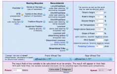
These real-world results are right in line with the bicycle speed calculator's predicted 22mph at 400 watts. The 2 mph difference is no doubt due to electrical inefficiencies the calculator does not account for.
 

Attachments

  • Clipboard5.gif
    Clipboard5.gif
    101.6 KB · Views: 4,274
"Each cell has to carry the same load either way."

This is where we differ. When you get 10 amps at low speed from 36 volts, (If you parallel the batteries) each cell only delivers 5 amps. If you have them in series at 72 volts, each cell delivers 10 amps.

When you exceed the 36 volt speed, switch to 72 volts. You save half the Amp-Hours when you are in the parallel mode.

Don
 
"Each cell has to carry the same load either way."

This is where we differ.

Ok. At least we're clear on where we disagree.

I'm going to use my system for this example. Let me know if you think it fundamentally different for other systems. I'm going to define each parallel bank of my batteries as putting out 4 volts, though the range is 3.6-4.2.

1) I have 20 banks of 15 cells. Each discrete bank of 15-cells is wired in parallel. I like to call these banks "subpacks". When these banks of paralleled-cells are wired together in series, I call that my "pack".

2) Each cell is 2.2 amp-hours and 4 volts. Therefore each subpack has 33 amp-hours of capacity (15 x 2.2 amp-hours), at 4 volts.

3)I could wire two subpacks together in parallel to create a 66ah 4 volt super-subpack, and I since I have 20 subpacks, I could do this 10 times, wiring 10 "super-subpacks" in series to create a 40-volt 66ah "pack".

4)Or I could wire all 20 subpacks together in series to create an 80 volt, 33ah pack.

5)Either way, my pack is the same watt-hours of capacity. Let's see how many:

a) 66 amp-hours X 40 volts = 2,640 watt hours

b) 33 amp-hours X 80 volts = 2,640 watt hours

this makes sense because I've got 300, 2.2ah 4 volts batteries either way and 300 X 2.2 amp-hours X 4 volts = 2,640 watt hours of energy.

With me so far? Are we in agreement so far?

5)So let's say I'm cruising down the road at 20mph with my 66 amp-hour 40 volt pack. That bike calculator, and my on-board ammeter, both tell me I need to suck from my pack a steady 10 amps to maintain this 20mph.

Agreed?

6)This means that each 30-cell "super sub-pack" is contributing 10 amps at 4 volts and each cell is contributing 1/3rd of an amp (10 amps / 30 cells). The volts then add together for 40 volts at 10 amps which equals 400 watts.

Agreed?

7)So each cell in this 40 volt 66ah pack is contributing 1/3rd of an amp.

8 ) If instead I'm cruising down the same road at the same 20mph with my 33 amp-hour 80 volt pack, that bike calculator, and my on-board ammeter, both tell me I need to suck from my pack a steady 5 amps to maintain this 20mph.

9) This means that each 15-cell sub-pack is contributing 5 amps at 4 volts, and each cell is contributing 1/3rd of an amp (5 amps / 15 cells). The volts then add together for 80 volts at 5 amps which equals 400 watts.

10)So each cell in this 80 volt 33ah pack is contributing 1/3rd of an amp.

Line 7 = Line 10, and would for any battery chemistry and arrangement where the voltage is halved and the paralleled-cell capacity is doubled (meaning total energy available for the entire pack is constant).
 
The equalizer in your " Specific " situation is that your motor runs better at higher voltage.... 5 amps at 80v.. or 10 amps at 40v... equals things out.. so the amp load on each cell is the same..

If you max out the controllers max amps, then it makes a difference. As the pack has to provide 20 or 40 amps depending on the controller.. at what ever voltage.
 
The equalizer in your " Specific " situation is that your motor runs better at higher voltage.... 5 amps at 80v.. or 10 amps at 40v... equals things out.. so the amp load on each cell is the same..

All motors are the same in this respect. Doubling the volts and halving the amps gets the same amount of power to the motor. When there's a load (as there always is to varying degrees) it's the power that's proportionate to speed, not just the amps and not just the volts. The hubmotor simulator also clearly demonstrates this.
http://www.ebikes.ca/simulator/
Find the peak power for your system, and then plug that number into the "bicycle speed and power calculator" to find the top speed you can expect to achieve on a given incline:
http://www.kreuzotter.de/english/espeed.htm

Notice the calculator does not care the amps/volts, only their product, the power.
 
There is a tiny advantage to running a lower voltage if you're going slow. The greater the difference between the pack voltage and what the motor's getting, the more losses there are in the inductor (controller).

I don't think the difference is very big, and usually not worth the bother of a dual voltage switch.
 
Current Limits are often associated with motor limitations and battery limitations. If you want to boost low end torque and your motor can handle the extra amps then the lower voltage / higher amps scenerio might give an advantage.

It comes down to "powerband shape".

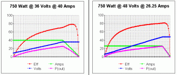
For the same total power output in "Watts" you can either have a powerband that is powerful at lower rpms or one that peaks late in the rpms. Efficiency goes up with rpms so from the efficiency standpoint the high revving, high voltage, low amps scenario is better. But for sheer low end torque (that's shifted because of the fact you are further up the parabola of power) you are better off with less voltage, but more amps.

Gears allow you to use the "peaky" powerbands better. You get higher efficiency and you "find" torque with the gears and not the motors powerband.

:arrow: Do you want an Indy Car or a Tractor?
 

Attachments

  • 36Volts verse 48 Volts.gif
    36Volts verse 48 Volts.gif
    12.7 KB · Views: 2,468
"8 ) If instead I'm cruising down the same road at the same 20mph with my 33 amp-hour 80 volt pack, that bike calculator, and my on-board ammeter, both tell me I need to suck from my pack a steady 5 amps to maintain this 20mph. "

You either have a magic motor or a magic controller.

If your motor is magic, it is a dual winding motor that magically switches from parallel mode when you have 40 volts on it to series mode when you have 80 volts connected to it. That way you would have 5 amps in each winding at your 20 mph condition and you would efficiently use your batteries would be used efficiently.

If you have a magic controller, It has a current multiplier (RC circuit) that takes the 5 amps from the 80 volt batteries and changes it to 10 amps before it sends it to the motor. This has been discussed before, but I have not seen a controller that claims to do it.

You can get a hint of what happens in the motor by looking at the performance numbers at the Crystallite web site. The data is not what you need to compare the performance because they do not have part throttle performance. The best you can get from the data is that torque is proportional to current (friction losses and winding losses not included).

The calculator only gives you what actual (delivered) power you need at 20 mph, so it does not care how you get it. You can't use it in your comparison.

Your volt times amp calculation only tells how much power is taken from the battery. It does NOT tell how much power the motor delivers to the road.

Now tell me about your magic motor and magic controller.

Don
 
You either have a magic motor or a magic controller.

Now tell me about your magic motor and magic controller.

Don

I've done all the explaining I can do. It's simple, practical math at work, not magic. Fechter noted there's a slight advantage at low speeds to going with low voltage/high amperage versus high voltage/low amps.

There is a tiny advantage to running a lower voltage if you're going slow. The greater the difference between the pack voltage and what the motor's getting, the more losses there are in the inductor (controller).

I don't think the difference is very big, and usually not worth the bother of a dual voltage switch.
 
The "Hub Motor Simulator" is an idealized 100% efficient "Magic controller".

Who sells them????

Don
 
:arrow: It's math.... that's all.

Go back and look at the charts I posted. For the same power output (and the same motor) you get different "powerband shapes". That's all there is to it! You lose a little more in efficiency with the lower voltage, but you get more power at lower rpms.
 
Back
Top