2 speed mid-drive build

ksithumper

100 mW
Joined
Oct 24, 2014
Messages
45
Ok, here is the background and the plan...such as it is... :D

Now and then I ride an old hardtail mtb on the trails with my teenage sons (and yes, they are much quicker than me). None of us have ridden an electric bicycle, but figure there is some fun to be had...

The idea is therefore to build a powered enduro/XC type MTB to help in two ways: to add range and take away some of the strain on long uphill climbs on the open trails (and any road liaison sections), and to assist on narrow trials-type technical going where gradients/deep mud/rock steps/fallen logs etc conspire to overcome my pedal ability. High road speed is not an issue, 25mph is ample.

With zero e-bike experience, I can't properly specify my needs but, understanding that 1 human power is of the order of 350 watts, I am pretty sure that 250W additional isn't going to be enough. Equally I'm NOT trying to build an electric motorcycle - I want a light/stealthy/assisted MTB with maybe 20-30 miles powered range. Something like 1kW feels right?

The plan therefore is to build a v.1 hack, as a fun learning exercise with my sons and to calibrate power/range/our expectations. Then we'll build a 'proper' v.2 full suspension bike to suit the drivetrain. A hub motor might conceivably meet the needs but instinct says a mid drive is the way to go, so we'll start there. Stealth implies a physically small motor, and that is likely to need 2 or 3 gears to cover my load/speed range. It seems that a robust 2 speed gearbox is something of a holy grail, so let's build one!!

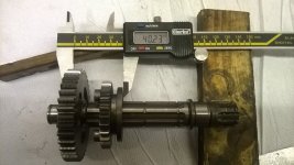
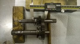
We started today with a Kawasaki KX65 cc bottom end. It has a 6 speed constant mesh gearbox. The speed range between 1st and 6th is approx. 2.62:1, so if we geared for ca 25mph in top gear then 1st gear is good for 8-9 mph - and it should still pull well at half that speed for the technical sections. 1st and 6th it is then. Riding later may show the need for an interim gear, or not.

This gear pair is only 40mm wide. A good start. Pics to follow when I work out how to upload!!
 
Output shaft with gears.
 

Attachments

  • WP_20141102_010small.jpg
    WP_20141102_010small.jpg
    114.9 KB · Views: 6,060
Hi Ksi..
Looks interesting. I think that a compact, light 2 or 3 speed gearbox coupled with a good electric motor could offer some real advantages.
For my build I have chosen a larger motor that I hope will give good torque at all speeds, but a smaller motor able to spin at higher rpm at low speeds would probably be more efficient.
I have been following Ecobogan's build with great interest. Obviously he does not need 6 close ratio gears, so what you are working on offers the advantages with less weight and size.
Good luck with your project.. I will be following it.
Dave
 
Thanks Dave, I'm following your build too - some very good work on this forum!

More progress:

one of the gears I needed was paired with another. To save weight and space I cut it in half with a very thin disc in the angle grinder, cleaned up the face on my bench grinder then linished it by hand on some wet and dry paper on a flat surface. Surprisingly good finish, more than accurate enough for a non-running surface.

Next I needed one more sliding dog but I have no easy way to cut splines. I decided to use a redundant gear with the correct dogs and splines, and add a groove in it for the shift fork. It is too hard to machine in my lathe so after a bit of head scratching, I used a dremel grinder mounted in the cross slide with a mini grinding wheel. To my amazement it worked really well!! Now I have a functional 2 speed gear set, all in 40mm width. It fits in just one half of the motorcycle crankcase, easily.

My original plan was to use this crankcase, with the motor sitting where the crankshaft was and using the motorcycle primary drive (as ecobogan has done so well). However, it is an ugly shape and heavy too... so I will make a new housing and use a belt primary.

If my prelim belt selection is right, I should be able to get a 1.5kW 'power block' of motor, primary drive and gearbox all in a space of circa 150 x 80 x 90 mm :shock: ...though the gearchange mechanism remains a challenge.

Bearings are on order, next step is a mock up followed by cutting the two shafts to length. More angle grinder fun :mrgreen:
 

Attachments

  • box small.jpg
    box small.jpg
    88.4 KB · Views: 5,797
  • grinding small.jpg
    grinding small.jpg
    71.8 KB · Views: 5,797
  • new slider small.jpg
    new slider small.jpg
    75.6 KB · Views: 5,797
I like what you're doing, and I encourage you to continue. Just for reference, ES member Thud built several 2-speed transmissions, and he may have some valuable advice to speed up and improve your version 2.0...should you move to that point after finishing V1.

"2-speed systems (R-D, dog-clutch or derailleur changing)"
http://endless-sphere.com/forums/viewtopic.php?f=28&t=8644&start=150#p195730
 
Hi KSI, good work.
Those thin cutoff discs are certainly a good invention.. I keep finding new ways / reasons to use them.

Nice work with the Dremel.. how long did it take to form the groove?
You could probably mount the Dremel across the lathe and use it to grind the face of the hand-cut gear if it needed to be truly flat, as well.
You might be able to lose a bit of width on the back of the new dog clutch with the cut-off disc in the grinder again. looks like you could save 3mm or so?

Assuming in your picture the calipers are measuring the gearset on the input shaft:
When the smaller gear / dog clutch on the output shaft slides away from the larger gear to allow it to freewheel, the smaller gear may not mesh with the larger gear on the input shaft across its full width. To achieve this may need the larger gear on the input shaft spaced a few mm away from the fixed small gear beside it.

A bit hard to tell the distances and clearances from a photo, much easier when holding it in your hand, so I could be wrong.

Working out the gear selector mechanism to slide the dog clutches will be fun. With a bit of luck, two of the grooves of the original selector cam might do what you want.

Getting the shaft centres correct and the shafts parallel when you make the new side plates of the gearbox will be really important. Looks as though you know what you are doing though.

Cool project.

Dave
 
spinningmagnets said:
I like what you're doing, and I encourage you to continue. just for reference, ES member Thud built several 2-speed transmissions, and he may have some valuable advice to speed up and improve your version 2.0...should you move to that point after finishing V1.

Thanks for the encouragement, I had read Thud's threads and like so many people on here he has some great skills and ideas.

I note Thud is an old motocrosser and was fighting the urge to built a high power crazybike. That is my story too! I have to keep reminding myself this is 'just' an e-mtb project, and I must avoid mission creep into the 10kW+ world! Luckily my son is an avid mtb rider; he just rolls his eyes at some of my mad ideas and points me back to the path we should be on. (Our frame design discussions are hilarious, but that is another story)
 
Drum said:
Hi KSI, good work.
Nice work with the Dremel.. how long did it take to form the groove?

Assuming in your picture the calipers are measuring the gearset on the input shaft:
When the smaller gear / dog clutch on the output shaft slides away from the larger gear to allow it to freewheel, the smaller gear may not mesh with the larger gear on the input shaft across its full width. To achieve this may need the larger gear on the input shaft spaced a few mm away from the fixed small gear beside it.

Hi Dave,
Again, thanks for the encouragement. Cutting the groove with the Demel took about 20min, just feeding it in gently about a thou at a time. Initially I just had the lathe chuck free to rotate but when I powered it up, in the opposite direction to the grinding wheel, it seemed to cut better. No noticeable wear on the grinding wheel.
I did use the Dremel on the face of the cut-off gear too, it was fairly slow so it was quicker just to flat it on the bench grinder by hand.
Re the gears, the meshing of both pairs is unchanged from the motorcycle. You are correct, the top shaft in the pic is the input. The cluster is shown in neutral. For high gear the top left dog moves right and the gear pair drives on the full face width. In low the bottom left gear moves right and dogs engage the bottom right gear into drive. The left gear remains in mesh across about 1/4 of its face, but the gear above it is freewheeling. Hope that makes some kind of sense?!

As for selectors, we have about 5 ideas, one really neat if it works. I don't want to use the original shift drum as it is relatively large and heavy (cast iron). Space is the challenge. We'll see.
 
Hi again..
Now I am home and using my big monitor I see what I missed first time on the small screen of my laptop.. the big gear on the output shaft is recessed on the face next to the smaller gear, so is disengaged in the position shown in the photo. I had thought it was flat, and therefore the dog clutch was engaged.
Sorry about that.. all looking good.

Are you hoping to change gear really easily, quickly and often like on a dirt bike, or are you willing to take a bit longer to do the change? And where are you thinking of putting the change mechanism? A foot operated lever like on a motorbike makes less sense if your feet are on pedals.. maybe a left hand twist grip with 2 cables?? Electric solenoid shifting?? Modified bike shifter like those used for derailleurs?? All sorts of possibilities.. looking forward to seeing what you come up with.

I also have 2 sons into MTBs, one of them quite seriously. Neither have followed me into mechanical engineering but both have a good understanding of how things work.. very good at giving my wilder ideas a reality check. And no, I can't keep up with them any more either!
I'm just building up a bike for my 13 yr old daughter.. I might be able to keep up with her for a while longer!?!
 
So, we had a little play tonight to get a feel for how much force is needed to move the selector forks.

My wife has now contributed to the project (I stole a chopping board from the kitchen). This was, er, chopped up to make 2 end plates. We lashed together a test rig with the shafts just running rough on nylon bushes, added a squirt of lube, and drove it with an electric drill. The video shows running in neutral, then 1st gear, then 2nd, then back to neutral.

The answer is 'very little force needed', so our planned gearchange mechanism should work nicely. Although there is no real load on the motor in our test, grabbing the shafts and making the drill groan didn't appreciably change the šelector force. It is easier still at higher speed, the gears snick in and out very nicely.

Reminding myself this is a bicycle and NOT a motorbike, I envisage normally high gear for the road and open trails, switching to low gear when we get to the tricky/slow/steep stuff where the motor would otherwise slow down and get overloaded. I guess I will normally be pedalling throughout, so I don't think shift dynamics matter overly much, though there is no reason changes can't be quick. What IS important is that it is robust and fail safe, ie there is no realistic selector failure mode allowing both gears to engage together etc. I definitely don't fancy a lock up at 40km/h on the street just as a truck is passing...!

We think we've cracked it though, and we are happy to move on to the next stage. Time to buy some ally to make a gearbox casing :D
 

Attachments

  • 2 speed.mp4
    2.9 MB
Hi Ksi, Looking really good. not much force needed to shift, so more options on gearchange mechanisms.
I hope your wife feels good that she has contributed to the project.. It's good when whole families share a project!
Agreed.. very important that neutral always happens between first and second.. locking the back wheel at speed isn't a good idea...
If you had a freewheel in the drive, locking the gearbox wouldn't be such a problem (if you could find a strong enough freewheel).

However my personal preference is for "solid" drive and regen braking available. Until I get my bike going I won't know for sure how well it works, but I will have analogue control on the amount of regen, using a left-hand thumb throttle. I should be able to pull up to 1.5kW out of the back wheel through regen if my information / calculations are correct, and that should be more than enough.. with the weight transfer towards the front during deceleration I imagine that amount of regen would break traction on the back. I generally ride in steep country (the flat land in my area is mostly urban or farming) so regen will extend my range far more than if I rode on the flat.

Watching with interest!
Dave
 
Hi Dave,

I guess I could probably find a freewheel that would cope with 1kW or so, but agree with you that regen is more important.The big plus for me is to add range to a day out on the trail, its pretty hilly where I live and I'm sure I can get some regen benefit.

I haven't worked out whether there is more regen to be had, at moderate speeds, by using low gear and spinning the motor faster ? Perhaps someone who is smarter than me with the electrickery (that's most of you :D ) can comment. If so, that is potentially a side benefit of a gearbox.

You are much further on with your build than I am, so once you have done a bit oftesting, do let me know!
 
Looking better than good, very slick on the shifting. My running the stock mx shift lever is a bit of a hassle, going to lighten the return spring and make it cable or solenoid operated. What have you worked out for the shift mechanism itself? I'm interested to see how the motor behaves, loadwise, from 1st to 6th gear. I know I couldn't jump from 1st to top under peak loads without it throwing a wobbly. Seems to be happiest 1st, 3rd and 5th/6th. Depends a lot on the purpose of the bike too.
If it's not MUCH MUCH more work to do a 3 (or very wide ratio 4) speed then you have possibly solved the gearbox E mountain bike conundrum.
Keep it up, for the common good even.
 
Yes , it will be interesting to see if the gap between the 2 gears is too wide, I'm hoping not, as long as I am pedalling too.

I chose the widest possible gear range to provide a reasonable road speed and also a very low off-road 'trials riding' gear. Its a possibility that I find I spend much of the time in the 'hole' in between gears. That's what this initial build is all about - experimenting to define what I really need, since to date the only electric vehicle I've ever tried is a Segway (and I fell off that :oops: ).

If needed, there are plenty of options. I can:
- alter the final drive ratio up or down accordingly
- use the 2nd and/or 5th gear pairs to close the ratio gap
- add a middle gear if necessary.

For my bicycle case, I think its more about choosing one or the other gear depending on the terrain, rather than driving like a car or motorcycle and accelerating up through the gears. I can believe that might need 3 gears unless the motor and ESC are man enough to pull low revs/high gear without damage. Interestingly some people on here, all of them way more experienced than me, say a well sized motor and single gear is all you need. My instinct is that may work on the road, but off road you need at least 6:1 speed range (from walking pace 6km/h up to say 35-40km/h). That motor would have to be pretty robust to endure full torque down at say 15% speed without meltdown. You can doubtless do it, but the motor is going to be big and heavy I think...and not terribly efficient at slow speed either.

Interesting that the KTM freeride offroad e-motorcycle has a single gear, but they had to add water cooling during development. I bet that was driven by the low rpm running rather than peak power.

As for your gearchange, I'd be very tempted to use a solenoid - like a road race quickshifter. No need then to modify anything internal, which is good as all those parts are well developed and robust thanks to Mr Kawasaki. My 2nd choice would be a push /pull left hand cable twistgrip to actuate the existing gear lever.
 
maybe one of these gear sets(or old engine) would be a good starting point.....https://www.youtube.com/watch?v=4iteP-zLsN8

3 or 4sp....nice and simple, use the shift drum with a lever attached to it cable driven from a 3sp derailleur shifter...shift drum spring might need some revision.

something I have been pondering after watching ecobogans video and hub failure, maybe a slipper clutch on the output shaft could be handy to reduce the sudden hit from being in low gearing or a jolted landing etc etc.

In my mind the clutch would slip easier in shorter gear ratios and less in top or taller gears.....but I aint no engineer :lol:
 
A frustrating day today. We had access to a milling machine but could not do the machining as planned; we need some additional tooling to accurately machine some of the bearing bores, there are 4 sizes and ideally 2 should be blind.

Then tried to work it out on a lathe but ran into different issues that mean we could machine the bores, but don't have confidence we could achieve the relative positional accuracy and alignment we'd like. (If it's not exactly right, worst case is the shafts will run tight, best case is a risk of rapid bearing wear). Previous experience says "it is time to stop and rethink".

Bad news: 4 hours wasted.

Good news: got permission tonight from the Director of Domestic Affairs to order myself a Christmas present, a very nice adjustable boring bar. :D
 

Attachments

  • 42949.jpg
    42949.jpg
    14.8 KB · Views: 5,130
Rodgah, thanks for the input. A Honda C90 or similar gearbox may be a good start, my concern was that they are a low power engine (5kW) compared to a race engine like the Kawasaki KX65(11-12kW). It would however certainly be durable enough for my case, maybe not for some of the big power guys?

I'm not using the drum shifter - too bulky and heavy ( a big lump of cast iron).

Clutches tend to slip more in higher gears when driving, so presumably the opposite when braking. My experience of many years of motocross is that a good chain tensioner is the simplest/lightest/best way to take the rapid shocks out of the drivetrain. An rc motor has so little rotational inertia compared to an ice engine (think crankshaft, flywheel, clutch) that I suspect the drivetrain will have a very easy time... but time will tell!
 
Hi folks,
sorry for the long delay since the last post- other stuff got in the way!

Santa brought my lovely new adjustable boring head, and using that it was a straight forward job to bore the various bearing locations.

WP_20141203_004.jpg

Today we borrowed time on a milling machine and machined the edges of the two gearbox casings . (The two drills you may see are used as dowels to keep the bores concentric), and also the spacer plates which will provide rigidity.

View attachment 2 WP_20150107_005.jpg

The pic with the coke can shows roughly how it will look and the scale. Not bad for a 2kW 2 speed powerplant!

WP_20150107_008.jpg

Plenty more to do, we'll try to keep it flowing now :)

good luck to all of you with your 2015 projects!
 
I encourage you to take lots of pics of the process. I can't promise anything, but I often find it helpful to use pics from projects like this in article for electricbike.com. Go to electricbike.com and check out the custom build links at the bottom of the 2014 end-of-the-year wrap-up article at the bottom of the front page
 
spinningmagnets said:
I encourage you to take lots of pics of the process. I can't promise anything, but I often find it helpful to use pics from projects like this in article for electricbike.com. Go to electricbike.com and check out the custom build links at the bottom of the 2014 end-of-the-year wrap-up article at the bottom of the front page

Ron, thanks for your interest. I have lots of photos - just a few on here, and at low res. I'll take plenty more as the project continues!

I should maybe better explain the gearbox casing concept - the whole oval will be wrapped in aluminium sheet to create a sealed oil containing unit. If eventually we learn that a 3rd gear is necessary or useful, we can increase the spacer width accordingly, but keep the same side plates. That avoids starting again completely.

This is all a first build, to go into a cheap hacked-around bike frame, to learn what we can and better define our needs. Then we'll do a more elegant v2, in a custom frame which hopefully will be trick - I am fortunate to have a close friend who is a frame building genius and my son is learning the art. Take a look at my last project which was a ground- up build... (sorry, it has an ICE!)
DSC08354a.JPG
 
LegendLength said:
Do you know the rough difference in weight between the original kx bottom end and the final version you are making with gears stripped out etc.?

Hi, an accurate figure is not possible, as I did not have both halves of the original crankcase - and the new version is also far from finished.

However, after borrowing the kitchen digital scales (sssh! :wink: ) my best estimates for the gearbox only (excluding primary drive) are:

Original 6 speed: 5.4kg
New 2 speed: 1.8kg
Saving: 3.6kg (66%!)

If it is necessary to add one more gear pair to make a 3 speed, that would be around 400g more, including an extra selector fork.

3.6kG is worth about 600Wh of LiPo capacity I think?

The advantage is not only weight but also volume, especially width which is important for a bike with pedals, and the easier integration to an existing bicycle.
 
Some more progress to share...

My son used the Dremel grinder in the lathe again to cut the shafts down to the correct length, using a very thin disc. (it is too hard to cut or machine with conventional lathe tools). It looks very pretty with the lights off!

cutting output shaft.jpg


Then he repeated the process at the other end of the shaft - it gives a surprisingly clean cut.

other end of output shaft.jpg


Here you now see the output shaft assembly complete with gears and bearings at both ends. The final drive sprocket will be on the right.

output shaft assembly.jpg


A similar process was used on the input shaft, and we also needed to cut a circlip groove...more Dremel successs!..and also machine up a small spacer.

new circlip groove cut on input shaft.jpg


This is the fully assembled input shaft. From the left: bearing, low gear, high gear, selector, circlip, spacer, and bearing.

input shaft assembly.jpg


Next steps will be to finalise the casing assembly, then work on the primary belt reduction.
 
Nice project. Th gear spread for a two speed mountain drive would be 2:1 ideally. If u dont do so many mountains then 1:1.6 would be fine (more street work)

I would go for a motor with many pole pairs and thin lamination like the MAC, rotomax 150cc or (0.2mm lams) ca120.

All of these motors need some rework in terms of adding halls or mounting... still i think all of them are worth the effort since you gain a lot of efficiency over a big block ir some other low pole count motor with cheap 0.5mm lamination
 
Back
Top