2020/21 What's the best 100A Peak Pack?

john61ct said:
I actually want to "productize" a generic current limiter for exactly that use case
plugging large depleted sub-packs back into the Full "mother bank" in parallel.

My second example would work. A length of wire in series will act as a current limiter. Or a power resistor on a good heat sink. There might be a better way, think some of the "mother banks" power heats the wire or resistor never making it to the sub pack.

There is a device that does exactly that, but only for up to 8P packs or 32V max input. It's a called a PowerLab.

http://www.usastore.revolectrix.com/Products_2/Cellpro-Series-Chargers-and-Battery-Workstations

This is what I use for cell testing with a PC interface. It works both directions, you can charge a test pack from the input supply, and if the input is a battery, you then can turn around and discharge the newly charged pack back into the battery.

It logs the data and natively produces graphs like this one:
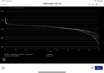
F610CF0B-EBE4-454E-A3CD-12182BB15207.png

The logs can be transferred to Excel for custom graphs, like this one:

EF3599F3-2FE5-45BA-A562-72C117E53069.jpeg

That one has data from a full constant rate charge and discharge cycle. Not sure what the rate was on this sample, probably .2 or .3C But is was the same throughout. I was attempting to devise an algorithm for my homegrown BMS to approximate SOC based on real-time Voltage and Current measurements. The BMS worked, but this SOC calculation never did. I also had a Coulomb counter based SOC, it was far more accurate.
 
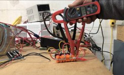
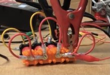
Well...I ran a test of the Gibson analysis. The paper linked earlier in the thread that discusses paralleled batteries where the further from the load, the less current is drawn, causing unequal utilization. I attempted to duplicate the analysis in the lab, but with 4 NCR18650 cells. The setup looks like this:

BC3D6011-F99D-4A5B-B63B-B03ED6C700E5.jpeg

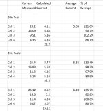
The foreground is the 4 cells, connected in parallel with AWG 16 wire. No bus bars. The cells were discharged at 20 and 25A. Measurements recorded the current sent to the pack, then each cell further from the load. Calculations determined the current load from each cell.

4BE3EFFE-60E4-4D08-B401-EBA14FFD4911.jpeg

I saw some of what I expected. The cell closest to the load carried more current. The furtherest from the load cell the least current. However, it wasn't consistent. Why is Cell 3 showing more current than Cell 2?

I wonder if that's because of variations in internal resistance of the cells themselves? Will rearrange cells and see what happens. Or am I missing something else?

I recorded the results of one of the tests and posted on YouTube, the link below.

https://www.youtube.com/watch?v=8BVNJqtPPgo
 
I would not trust vruzend contacts. Its hard to say if all cells have same contact resistance. Better to have them spotwelded and your parallel wires connected to nickel.
Wander if there are hall current sensors that could be soldered between cells to reduce distance between cells as this scenario is not realistic, at least on small cylindrical cells
 
I should have said the cells were the GA variety. The 4P20S pack I built almost 2 years ago only has a few cycles, but remains flawless in sync, with normal charges to only 81V, which is below the threshold for the BMS to balance. This pack is limited to 60A, both by a circuit breaker and a CA3.

The cells in this test though "new", are not fresh, and have been sitting for 2 years in the shipping box they came in.

agniusm said:
I would not trust vruzend contacts. Its hard to say if all cells have same contact resistance. Better to have them spotwelded and your parallel wires connected to nickel.
Wander if there are hall current sensors that could be soldered between cells to reduce distance between cells as this scenario is not realistic, at least on small cylindrical cells

This is also a good possibility. Even with bolts and ring terminals, I've seen several packs show huge differences in internal resistance as measured by the BMS and also in this testing rig. In all cases, it was a poor connection, repaired by reseating all connections around that cell. In this case, that measurement is of no use, since it applies to all 4 cells as a unit, with no adjacent cell as a basis for comparison.

I don't have a welder or I might sacrifice these cells in the name of science....:)

What I do have is a box of fresh Headway cells with mechanical fasteners. Cells dated 12/25/2020. I guess they don't take Christmas as a holiday in China. When I finish with my 4 cell, 1P4S 12.8V setup for capacity testing, I will reconfigure to 4P and try this test.

Going back to the reference article, the prediction was the first cell would carry 36% vs the last cells 18% of the total load. While this test is still flawed, I showed 33% and 20%. I see no reason to believe this ballpark level of load difference will equalize. So if you are using cells with a 500 cycle life, the first cell in the group gets roughly 50% more work than the last. Does that matter to overall pack life?

I'll speculate here....maybe not as much as you might expect. The first cell would age faster, lose more capacity than the cells further down the chain. But then, regardless of the connection difference, the less aged cells would begin to carry more of the load.

Where it would matter, is if you were building a pack to produce 100A. And the cell's discharge limitation was 25A. To remain within limits, 4P isn't enough. You would need a cell with a discharge limit of 33A. That's not insignificant.

If I remember right, the limitation for the NCR18650GA is 10A. The 72V pack I built for my eBike at 60A already exceeds this limitation by allowing 15A per cell. The rationalization is it doesn't happen except for peaks. Connected like this it would see more like 20A at a peak 60A load. At some point, it probably matters.

100A in a shoebox sized pack isn't easy....unless you build it at 36V, which defeats the purpose!
 
My new just arrived is my Samsung 40t 30amp cell 20s6p on paper 180amp pack I use at 90 amps tops. This is how I think for longevity and voltage drop.
Order a N.E.S.E kit 8p 14s to go with Samsung 30q 15amp cell so 120amp to be use at 80 amp at the most. So leave so headroom on discharge and charging lvc and hvc. Excuse me but I have to go downstairs now and test. Thanks Agniusm will put your kit to the test.
 
Although this is 60amp max continuous discharge (claimed) and not 100amp as requested in the title, I can't find a better deal than this: https://www.amazon.com/dp/B08NVXJQY9/?coliid=IAP7MAE8JA5G7&colid=1MR3P4LYET22V&ref_=lv_ov_lig_dp_it&th=1

But I'm not sure what battery cells they use. Possibly they use whatever is lying around. But the specs say 25amp discharge per cell and the picture of them has a lime green wrapping, I'm sure somebody here can identify them?

But let's say they're $3 per cell from batteryjunction or something similar (which would be a good deal).

72v 25ah would require a 20s10p config (right?) which is 300 cells x $3 = $900. Plus the cost of either a spot welder or kits from N.E.S.E. or Vruzent, a BMS, and a charger. You get all that for less than $750 already assembled, welded, wired, and wrapped.

[edit: 20 x 10 is 200 not 300 :oops: ]

Anybody have an opinion on that seller/builder? If all is well then I will probably order soon.
 
mannydantyla said:
72v 25ah would require a 20s10p config (right?) which is 300 cells x $3 = $900. Plus the cost of either a spot welder or kits from N.E.S.E. or Vruzent, a BMS, and a charger. You get all that for less than $750 already assembled, welded, wired, and wrapped.

Anybody have an opinion on that seller/builder? If all is well then I will probably order soon.

Yes 10P20S, which is 200, not 300 cells. Here are the cells:

https://www.alibaba.com/product-detail/Rechargeable-Lithium-ion-Battery-INR18650S-2500mAh_62348208534.html

At $1.15 each, that's $230 for the raw cells...plus shipping. Your shipping guess is probably better than mine.

As you mentioned...doesn't make the 100A requirement as I mentioned in the topic request. But neither did what I ended up using. 100A is not a value based configuration yet.....
 
mannydantyla said:
But I'm not sure what battery cells they use. Possibly they use whatever is lying around. But the specs say 25amp discharge per cell and the picture of them has a lime green wrapping, I'm sure somebody here can identify them?
Even if you can identify the ones in the picture, what guarantee do you have that you'll actually get those, vs some other random cell? :(

But let's say they're $3 per cell from batteryjunction or something similar (which would be a good deal).

72v 25ah would require a 20s10p config (right?) which is 300 cells x $3 = $900. Plus the cost of either a spot welder or kits from N.E.S.E. or Vruzent, a BMS, and a charger. You get all that for less than $750 already assembled, welded, wired, and wrapped.

Something to consider is that if a pack costs WAY less than it would cost you for the same capability pack (cells & BMS, at least, not including the welder/interconnects/etc), it is quite possibly just what it seems like--too good to be true. ;)

It is also unfortunate but likely that most pack builders do not match the cells they use to each other, so they are not all that likely to be equal in capability, and thus aren't as likely to stay in balance or perform as well over time as a pack that is made from well-matched cells of good quality.

After all the junk that's been posted here by various people for troubleshooting and repair over the last decade, plus my own two personal experiences with 18650 packs, I tend to be a little pessimistic. ;)
 
BlueSeas said:
Here are the cells:

https://www.alibaba.com/product-detail/Rechargeable-Lithium-ion-Battery-INR18650S-2500mAh_62348208534.html

Even worse than I assumed. I think I will be skipping on that battery pack.

How about this LiFePO4 pack? https://amzn.to/3sEW0Yl They say it's made with LG pouch cells. But the specs in the listing are very confusing and full of errors and conflicting figures. Like that the 20ah pack is heavier than the 30ah pack.

It's actually not even clear what kind of battery pack it is because in the title it says it's a "Lithium ion / LiFeO4 [sic] Battery Pack" and it says it uses 20 cells in series to get 72v. A LFP pack would need 23 or 24 cells in series to get 72v.

In general, are LiFePO4 packs more forgiving of quality issues than 18650 packs?
 
If you want LFP spend the money to get new A123 (now Lithium Werks).

Everything else is going to have half or a third the lifespan

and that's with known brands, trusted supplier genuine and actually new.

There is no bottom to poor quality coming out of China

but admittedly more "action" in that regard with the higher voltage and higher energy density Li-ion chemistries.

Apparently Mr. Ping delivers a very solid LFP pack, many years now, despite likely not using A123 anymore.
 
The biggest problem with rando sellers in these channels

is they usually have no technical understanding about what they are selling.

If anyone in the "company" does, they have little to no English, and employee can't ask questions internally without losing face and annoying management.
 
mannydantyla said:
It's actually not even clear what kind of battery pack it is because in the title it says it's a "Lithium ion / LiFeO4 [sic] Battery Pack" and it says it uses 20 cells in series to get 72v. A LFP pack would need 23 or 24 cells in series to get 72v.

In general, are LiFePO4 packs more forgiving of quality issues than 18650 packs?

I think of a 72V LiFePO4 (LFP) pack as 24S. But I can see where you could think 22 or 23S. The cell nominal voltage is 3.2V. By 3.0V, they might have 10% left.

LFP seems to survive in a niche. The chemistry more stable, meaning less variations. Key drawback, density. It will take more space, and weigh more compared to traditional 18650 3.6V cells. Advantages, theoretically more cycles, and a safety advantage, less likely to start fires. Maybe more forgiving, I'm not sure I can fully agree with that assertion. But having worked with Forzatec, CALB, Sinopoly, Thundersky, and GBS, there are far more similarities than differences. But haven't worked with the true pioneer brands like A123 and Ping. Bottom line, if space and weight aren't key considerations, worthy of consideration.

As previously stated, you usually get what you pay for. I was really hopeful that someone would emerge as the "Chevy" or "Ford" of battery packs. Good, mass produced, but probably not the best. However would provide a dependable cost effective choice for most of us. Luna was headed in that direction with their investment in pack building technology. But not sure it's panned out completely. As of today, only 1 of 3 different 72V options are available. Grin has tried to tackle this with their LiGo line. But it's still kinda pricy to be called cost effective. 13.5 Ah for $1200 plus shipping. Maybe someone else has a vendor with a track record?

Happy hunting!
 
The quality comes at a cost unless you buy in bulk. You either have a choice to pay the premium for ggod stuff or get cheap stuff from ebay/aliexpress/alibaba and endup with nothing.
 
agniusm said:
I would not trust vruzend contacts. Its hard to say if all cells have same contact resistance. Better to have them spotwelded and your parallel wires connected to nickel.
Wander if there are hall current sensors that could be soldered between cells to reduce distance between cells as this scenario is not realistic, at least on small cylindrical cells

You may be right. I finally found time to finish this testing. In fact right on this count and the overall premise of unequal load distribution.

When I broke apart the test cells from the initial configuration that looked like this:


61FBC7D8-93A7-421A-AEF4-8F6144B99975.jpeg

I rebuilt the test configuration to look like this (I forgot to snap a photo):


2F927D34-A23C-40AA-8D8D-A4E766D7A574.jpeg

First...when breaking apart the cells, one of the Vruzend caps had cracked. It was no longer securely holding the cell, so can't be sure there was a solid contact made, which could have influenced the original testing. The cap was replaced.

Went to this configuration to be able to use a clamp meter and directly read the current into each cell. Using 4 clamp meters at the same time, I could read them all simultaneously. The bus bars are Bluesea, rated at 100A. The load was a dummy electronic load tester usable up to 400W or 100A at 4V. Only ran one test at 20A. 5A per cell.

Cranked it up and read the 4 clamp meters. They read from 4.8 to 5.2 Amps. Not what I expected. That's near perfect distribution. The .4 amp variation within the margin of error for clamp meter readings. So second...you were also correct that Gibsons thesis (linked earlier in thread) would not apply.

This is a reasonable simulation of your pack building units. The bus bar much more robust here, but I don't think it would change the results significantly even if the bus bar was substantially smaller. So your right here too!
 
All of the above said. There is another study from the marine world at this link:

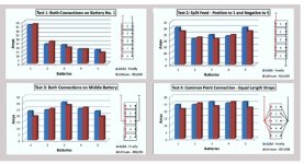
https://coastalclimatecontrol.com/index.php/blog/272-current-affairs-making-the-right-connections.html

They found this:

4F73CCDA-50D2-4BB7-9C9A-DE577C25CED5.jpeg

The test I did today, is closely aligned with test 4 above. A single bus, equal cable connections to each cell. I didn't use a power post, but it was close enough. Which is probably why I saw similar results.

It seems that "equal" connections are a major influence. In this test #4, and my test today, the connections to each battery and cell pass through the same number of "connections". In test #1 of this study, the last battery passes through many more cable crimps and post connections than the last battery. Each adds resistance. Cumulatively that adds up.

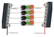
Is there a transfer to eBike pack design? I'm not sure now. I wonder about this comparison:

EB2973FE-D038-4023-B58C-52A3209BB0C6.jpeg

There would normally be a "bus strip" across all the paralleled cells, not shown, so that again sort of resembles today. But in the first example compared to the alternative, the effect if any, is multiplied.
 
BlueSeas said:
tor never making it to the sub pack.

There is a device that does exactly that, but only for up to 8P packs or 32V max input. It's a called a PowerLab.

http://www.usastore.revolectrix.com/Products_2/Cellpro-Series-Chargers-and-Battery-Workstations

This is what I use for cell testing with a PC interface. It works both directions, you can charge a test pack from the input supply, and if the input is a battery, you then can turn around and discharge the newly charged pack back into the battery.

It logs the data and natively produces graphs like this one:

They make the Powerlab in an up to 32s configuration. Just wanted you to know. You can do much more than 8s.

... just need a bigger Powerlab or two, than the 8s.
 
BlueSeas said:
This is a reasonable simulation of your pack building units. The bus bar much more robust here, but I don't think it would change the results significantly even if the bus bar was substantially smaller. So your right here too!

Even if you use larger busses vruzend contact is still a gamble. My bus bar tabs are smaller but the cells are constrained and have uniform pressure. Cant remember of the top of my head but something like 2.5kgf. I thought about this too when designing these modules and one of the three reasons no to go over 8P was uneven load even if its small.
 
DogDipstick said:
BlueSeas said:
tor never making it to the sub pack.

There is a device that does exactly that, but only for up to 8P packs or 32V max input. It's a called a PowerLab.

http://www.usastore.revolectrix.com/Products_2/Cellpro-Series-Chargers-and-Battery-Workstations

This is what I use for cell testing with a PC interface. It works both directions, you can charge a test pack from the input supply, and if the input is a battery, you then can turn around and discharge the newly charged pack back into the battery.

It logs the data and natively produces graphs like this one:

They make the Powerlab in an up to 32s configuration. Just wanted you to know. You can do much more than 8s.

... just need a bigger Powerlab or two, than the 8s.

I also see a typo of mine, I meant 8S not 8P. I didn't know you could stack Powerlab's in series. I use the Powerlab to test cells, not banks/packs. 4 cells at a time seems sufficient. What would be the application for a 32S Powerlab? One that using a Bluetooth BMS and a Grin Satiator doesn't already handle?
 
agniusm said:
Even if you use larger busses vruzend contact is still a gamble. My bus bar tabs are smaller but the cells are constrained and have uniform pressure. Cant remember of the top of my head but something like 2.5kgf. I thought about this too when designing these modules and one of the three reasons no to go over 8P was uneven load even if its small.

The biggest issue with Vruzend is using the screw as a conductor. It adds connections. The cell contact plate connects to the screw, which then again connects to the bus bar system. Your system has only 2 connections per cell (the cell contact itself) to join the bus bar highway, Vruzend has 6 connections. Then the "highway" has additional connections between each cell using stacked bus bars.

Every connection adds resistance. Resistance is bad by itself, but worse if unbalanced. Ideally, every cell should have the same number of connections between B- and B+ as every other cell in the pack. Note it's round trip, 3 connections to B+, 1 to B- is the same as zero connections to B+ and 4 connections to B-. And so on.

This recent test shows the space between cells on a common bus doesn't materially count as a connection. So every cell in the test had the same number of connections to the load. Maybe I will rerun this test, replacing the single Bluesea bus bar using stacked bus bars. If that doesn't produce a material difference, then there probably isn't any applicability of the marine studies to the way eBike packs are built.
 
BlueSeas said:
The biggest issue with Vruzend is using the screw as a conductor.
This recent test shows the space between cells on a common bus doesn't materially count as a connection. So every cell in the test had the same number of connections to the load. Maybe I will rerun this test, replacing the single Bluesea bus bar using stacked bus bars. If that doesn't produce a material difference, then there probably isn't any applicability of the marine studies to the way eBike packs a

Exactly that and i would clarify even more, load transfer through threads which is a big no no in all electric.
If you would examine, the current flows from the contact up the threaded rod, into the nut and then from the nut to the plate which was stainless at the beginning(dont know if that changed). To top it of it is clamped against plastic.
On my system conductor touches output directly and although plastic is also used it is just to clamp 2 conductors which carry the current
 
Blueseas I remember 10yrs ago with the ping lifepo4 packs some poeple would over demand from there packs and almost always puff the last cell in series next to load.
 
Back
Top