• Hello ES! We could use some help to get us past the finish line on building the new knowledgebase for the forum.
    Can you donate? Please see our fundraising page. Thank you!

7070 Outboard project. ESC, BMS, logging...

PoD

🧲 New user
Joined
Oct 10, 2025
Messages
9
Location
germany
Hi everyone,

I’ve been reading this forum for a few weeks now and have already found a lot of useful information, thank you for that. I’m currently preparing my very first electric vehicle project, but I’m still rather unsure about certain aspects of it, especially the electronics. So I have a few questions, and I’d really appreciate your help in bringing this project to life. That’s why I’m making my first post here today.


I want to design and build an outboard motor. For this purpose, I already have a FlipSky 7070 motor and a FlipSky 75100 Pro V2 ESC. The initial plan is to use this motor (no gears) to power a canoe. Based on my estimates, there is around 100–200 W needed. The target speed is 5–6 km/h.
Later on, I’d like to have the option to run the motor at full power in case I want to use it on a different boat. So the electronics need to be efficient but, above all, safe at lower and also higher loads.


I’ve read in several posts, around the internet, that some users managed to burn out their FlipSky ESCs, and I definitely want to avoid that.
Because of this, I’m planning to convert the ESC to water cooling. I saw in a YouTube video that the ESC board is only mounted at four points. I’m considering replacing the housing with a copper or aluminum base plate and increasing the number of mounting points to six or even eight.
Do you think this is a sensible modification?
My idea is to drill and tap holes to mount the ESC board, and have water flow through the opposite side of the plate.

However, a few questions arise:

Could this cause mechanical or thermal stress that might damage the board?

How much water flow would be necessary for effective cooling?

What kind of pump, flow rate, or pressure would you recommend for this ESC?


I’d also like to measure the energy consumption so I can experiment with different propellers and find the most efficient setup.
My idea is to configure the ESC for maximum efficiency, then test various propellers to locate the best propeller for the canoe.

Any tips on suitable measurement hardware or logging methods would be very helpful.


For the power supply, I plan to use a 13S 21700 lithium-ion battery pack.
I still have some questions about this as well—especially regarding which BMS would be suitable for this configuration.

Is a only charge BMS the way i should go?

Any recommendations or things I should watch out for?


I’m completely open to answering any questions and providing any details you might need. I’d really appreciate your guidance so I can build a safe, reliable, and efficient outboard motor.

Greetings from Germany
 
There's a few threads / posts about some of the flipsky controllers and why some of them failed. IIRC it was something to do with a function that the hardware wasnt' there for but got turned on in the settings anyway, but I don't recall the details. Flipsky is also not the highest-quality brand of VESC. I don't recall which series or which brand, but there is also one of htem that has a problem with the entire model/series whereas the next one down doesn't have that issue. It's discussed in a least a couple of threads somewhere here.


Regarding the water cooling, just be sure that whatever system you use leaves the electronics section fully sealed against environmental intrusion (this is pretty difficult to completely do). Put all the cooling *below* the electronics and wiring, so low-pressure leaks don't run down into the controller or wiring. All wiring needs to go upward away from the cooling stuff, all the cooling stuff needs to do downward away from the active parts. If you have to use high pressure cooling loops, you'll need to be pretty certain all connections and loops are secure against leaks. Low pressure is easier to manage, but even simple CPU / video card cooling systems are not-infrequent causes of liquid-cooled computer-system damage. :(

How much flow you need depends on the surface area of the coolant to the heatsink, and the rate of heat exchange between the heatsink and the electronics, and between the heatsink and the coolant. I'd recommend looking at various liquid-cooled heatsink designs; there are some here on ES that were custom made for their applications, and plenty elsewhere as well. You may be able to buy a bolt-on plate that does what you want, or you may have to make it or have it made.


Mehcanical / etc stress depends--if things expand and contract cyclically, this is what causes most types of damage to things over time. If temperature is kept constant then that cycling doesn't happen, and the stress damage doesn't happen. If the holes you're thinking of drilling are in whatever cooling block / heatsink then that would be fine, but if you are thinking of drilling into the controller, you need to be completely certain that there is nothing in those spots in any PCB layer before you do so. If you drill thru conductors or active electrical layers, you can render the controller useless.


As for maximum efficiency, that will depend on the actual loading and conditions, so you can make a "best guess" setup based on expected values, but you'll need to do the tuning under actual usage conditions (under load in the water).


Measurement hardware is basically built into the VESC already, for battery current, voltage, phases, so you just need to read that data and keep track of it. I would guess that the VESC control / setup software can do this, so you could probably run that on a phone or tablet connected to the VESC (probalby via BT or serial, maybe CANBus, don't know what options your controller has). There are quite a few VESC threads here some of which discuss that software or other "dashboards" for VESC. (not all of those discussions are in dedicated threads, so you might have to look thru other threads that have VESC as side-discussions; I don't have any links).


I don't know what the power requirements are; this depends on the shape of the boat hull and the water conditoins and the speed. HOpefully your data is right--that will mean a very low power usage.

For the battery, i fyou use a charge-only BMS, then there is no cell-level protection against overdischarge. Only pack level protection against the whole pack undervoltage, and whole pack overcurrent. If you are not charging it to full, and not discharging it to empty, say, no closer than 20% either way to those limits, then it will be more likely to keep all cells equal in voltage (balanced) even if they are not matched (identical properties--not close, but identical), and so be less likely to have a problem with this type of usage.


There are threads about and posts within various other threads about each of the different things above with more detailed info, too.
 
I wouldn't bother with water cooling the ESC, basically all of the burned out flipsky's are not from lack of cooling but from other issues. If a VESC is designed reasonably well (the flipsky is not but good enough) and setup correctly it you will not be able to burn it out from normal operation. It will just start cutting back power after it gets to the the temperature limit. You are better of building it and then running it and add more cooling only if you start get thermal throttling.

Now there are many reasons why ESCs do blow up, incorrect settings or poor hardware either causing current or voltage spikes, instability, sync loss, etc are what kills VESCs and more cooling is unlikely to stop any of those.

Oh and for waterproofing, I've waterproofed a few of those and generally first I open it up and conformal coat everything, then silicone the case shut sealing off all the wires. You can either make a case that covers the top half for the wires to go out or just silicone all the control wires sealed. I usuall make a case that covers just the top half with a gasket and seal cables leaving the case. That way the bottom where the heatsink is is open to air and I can open the case if needed to rewire things.
 
Based on my estimates, there is around 100–200 W needed. The target speed is 5–6 km/h.
Your estimate is reasonable.
I've push 11,5M sailboat at 5 km/h with 1000W.

Why don't use a motor support shaft in aluminum and in contact with water to cool down controller mount on this shaft (thermal transfers between controller and water via shaft/support)?
 
Hi everyone,

Sorry for the delay — I’ve been busy at work the last few days.
I’ve seen there are a few threads about this, but it all seems a bit confusing, and I really don’t want to damage my ESC. I know FlipSky might not be the best brand for VESCs, but it’s what I have now and I’d really like to use it.

Thanks a lot for the water-cooling tips. I’m planning to pack everything into a sealed, leak-proof box. I had considered CPU coolers, but I can’t really mount the ESC’s aluminum PCB on them — there doesn’t seem to be enough material to make proper taping for screws. In the original housing, the PCB is held by clamps, which apparently leaves a gap in the middle, so heat isn’t transferred properly. Since there are many variants of this ESC, I want to play it safe and water-cool it. I’ll mount the PCB using clamps on the outer edges, pressing it onto the base plate — but I’m planning to use six or eight clamps instead of just one in each corner.
Conformal coating is a great idea, and using a case that seals the upper half of the electronics seems sensible too.

Regarding the BMS, I think it might be smarter to use it only for charging, and connect the load directly to the battery when discharging, but not sure about this. That way, any current or voltage spikes won’t trigger the BMS or shut off the battery. I’m not just planning to use this motor for the canoe; later I might use it for a bigger boat, which would draw quite a lot of power — the motor can deliver up to 4.4 kW, which could mean 60–100 A.

A 11.5 m sailboat moving at 5 km/h with around 1000 W seems reasonable, and matches what I’ve seen from others online. Using an aluminum motor mount to help cool the controller is a good consideration. I like to use i-tem or bosch aluminum profile, say 20mm by 60mm or 40mm by 80mm.

For energy monitoring, I thought about using a GPS module. If the ESC’s CAN bus supports it, it could log speed and energy use. My plan is to run a propeller for half an hour or so at my target speed, log the data, and calculate energy consumption per kilometer to find the most efficient propeller. Any ideas?

Oh, and I wanted to ask — does it make any sense to install a hall sensor or something similar on the motor? I honestly have no idea, sorry about that, but that’s exactly why I’m looking for help here.

Are there any VESC settings I should definitely avoid, or is it better to stick with the default? Many videos I’ve seen on YouTube show setups for e-foils, where full power is required, or for e-bikes. But the e-bike setup doesn’t really match my use case, I think?! And regarding the VESC settings for my motor — should the same settings be used for low power (say 100–200 W) as for high power (2.2 kW or even 4.4 kW), or do I need to adjust them depending on the load? Sorry for this basic questions.

So far, I only have the motor and the ESC, and I haven’t connected or tested anything yet because I don’t want to risk frying anything. I’ve got some time — let’s say until next spring — and I really want to do this properly. I don’t want to build something that ends up breaking everything.

1.jpg

Greetings from Germany
 
Last edited:
I found this guy quite interesting as he test different propeller efficiency with flipsky controller: rctestflight
He generally give it 3D models for free.
Edit: I found this prop/Cat test interesting:

I will keep an eye on your project as I need to build something similar for our dinghy.
But I can't see how to obtain efficient motor/propeller combo with motor rpm in the 4000-5000 range.
From my search's, bigger prop turning lower rpm is more efficient than smaller prop at higher rpm.
 
Last edited:
Hi

Exactly — that’s where I got the propeller from. I’ve modified the motor hub and will experiment with the diameter and blade width until I find the propeller that works best.
The best result he got with it was 4–5 Wh/km at 1.5 m/s. That's pretty impressive..not?

Yes, that may be true, but I already have the motor, and adding a gearbox or belt drive would make things significantly more complicated. In general, I’d prefer to keep the motor underwater so it stays nice and quiet and I don’t have to constantly listen to the motor noise.
 
The best result he got with it was 4–5 Wh/km at 1.5 m/s. That's pretty impressive..not?
Absolutely, but everything is relative. My kid do the equivalent of 2-3 Wh/km at 2 m/s in bicycle 😆 ;)
His Cat hulls seem more efficient than a canoe.

Yes, that may be true, but I already have the motor, and adding a gearbox or belt drive would make things significantly more complicated.
Sure. It's where I have hard time to determine if the integration of an inline planetary gearbox underwater worth something significant.
Or, in my case, simply find a motor with lower KV to have a prop spinning in the 1500-2500 rpm range instead of 4000-5000 rpm.
Can't wait to see your design.
 
Yes, of course. The lighter the boat is and the lower the resistance, the less energy it will consume. Four watt-hours per kilometer is extremely low, so I’m expecting something more in the range of 20 to 40. I might add a second outrigger to the canoe, but overall I think I should be in the right ballpark with that estimate.


Sure, if you can find a motor that runs that slowly, that would be great. But right now I honestly wouldn’t know which motor that would be. And in my case, I already have the motor and I want to use that one anyway.


I honestly have no real knowledge about motors. It may well be that something like that exists. Maybe there are even one or two examples someone could mention here. That would definitely be interesting.


Using a planetary gearbox or an angle drive would honestly be too much effort for me at this point. And when I see that e-foils—which practically run at full power—manage without any reduction, I feel like it should work with the outboard motor as well. Of course it won’t be as efficient as it could theoretically be, but I’m trying to be as efficient as possible with the motor and ESC I already have. Not pushing everything to the absolute limit, but efficient enough without creating an excessive amount of extra work.”
 
Last edited:
Not pushing everything to the absolute limit, but efficient enough without creating an excessive amount of extra work
Nice! Don't hesitate to share more detail about your build.
I'm clearly interested to do something similar in the 2-5 kW range.
 
I would do a good job of waterproofing the ESC first, then test it and then worry about water cooling.

Also that type of motor responds very well to VESC so it should tune without too much fuss with the default settings in the setup wizard, given it's a prop application hall sensors won't really help.

I would go with a programmable BMS and connect the ESC through the BMS, you want the BMS to be able to trip in the event of something going wrong and a programmable one allows you to set the current to reasonable levels for the application and to set the time windows to prevent false alarms. You generally can set the over current to several windows so a short spike just above the max setting won't trigger it but a slightly longer current pull above the set limit will or a short spike that is much higher than the limit will. I would probably go with a JBD, LTT or JK BMS, they are all cheap and fairly well regarded.
 
Hi.

Okay, so today I didn’t just order a crimping tool, but also an aluminum PC cooler. I also added a 0.5 mm thermal pad, hoping that this will largely bring the whole water-cooling topic to a close.

Next, I’ll see if I can find a suitable enclosure—or maybe even 3D print one—to house the ESC and protect it from splash water. Additionally, silicone could be used to further isolate the cooler from the ESC.
I’m not sure yet—maybe the entire electronics could be potted in something, like resin or silicone or something along those lines. I’ll need to look into that. Of course, I’m open to any tips or suggestions.

Yeah, it’s good to hear that the VESC settings and this motor work well together.
And yes, regarding the BMS—I’ve already had JK BMS in mind. They’re obviously very affordable. What would you recommend: a 200 amp one, or would something with a lower rating be enough?

Then I have a more general question about the torqe and the battery voltage.
Does it make sense to maybe reduce the battery voltage to 24 volts in order to achieve higher torque and get a bit more efficiency out of the motor at this low power levels, or is that just nonsense?

✌️
 
I also added a 0.5 mm thermal pad, hoping that this will largely bring the whole water-cooling topic to a close.
If you mean a pad that goes between a heatsink and a heatsource, those slow down the rate of heat transfer vs bare metal-metal contact of a correctly-fitting / polished (lapped) set of surfaces. They do help in the case of poorly-fitting surfaces (as does thermal compound, at least until the liquids in the thermal compounds migrate out and leave air gaps).
 
Next, I’ll see if I can find a suitable enclosure—or maybe even 3D print one—to house the ESC and protect it from splash water. Additionally, silicone could be used to further isolate the cooler from the ESC.
I’m not sure yet—maybe the entire electronics could be potted in something, like resin or silicone or something along those lines. I’ll need to look into that. Of course, I’m open to any tips or suggestions.
Dipped/soaked conformal coat, or full potting, are a much more certain ways of keeping moisture out of the electronics than a sealed enclosure, as it is difficult to truly seal something--if there are wires that go thru it, it is possible for small air pressure changes to migrate moisture into / out of such an enclosure, via the spaces between the wires and even the spaces between the conductors inside the individual wires' insulation. That's typically a long-term issue, so it depends on your conditions and the intended lifespan of the system.


Repairs or modifications are easier for non-coated/potted systems, if that is a potential thing you'll need to do.
 
Then I have a more general question about the torqe and the battery voltage.
Does it make sense to maybe reduce the battery voltage to 24 volts in order to achieve higher torque and get a bit more efficiency out of the motor at this low power levels, or is that just nonsense?
Voltage doesn't directly have anything to do with torque, in that *lowering* the voltage will not *increase* torque.

Torque is phase current controlled. If the motor has a high resistance, then higher voltage can allow higher phase currents, as long as the controller itself is capable of supplying those.

I highly recommend experimenting with the motor simulator at ebikes.ca to see how this all works. Doesn't matter what system you choose there, just as long as you do the same relative things to it to see the relative results. You may have to vary the conditions from default to get sufficient loading, but keep those conditions the same between "runs". (or use the A/B compare mode).
 
And yes, regarding the BMS—I’ve already had JK BMS in mind. They’re obviously very affordable. What would you recommend: a 200 amp one, or would something with a lower rating be enough?
What is the max current you will ever need, in any usage of the system? That's what the BMS must be capable of supplying.

If it's programmable you can always turn the limit down so it shuts power off in the event of an excessive current draw. But you can't turn it up above hardware capabilities....
 
😲 :unsure: Really? Can you explain this?
I also have prop application with Nissan Leaf motor without sensor at the moment.
For this application the VESC should be able to run sensorless just fine with a outrunner motor like that and hall sensors would only be useful for startup but since it's a prop that's not really an issue. For an IPM motor like the leaf an encoder of some sort is better since VESC and controllers in general do not perform as well with IPM motors in sensorless and hall sensors only work well at lower RPM.

Yeah, it’s good to hear that the VESC settings and this motor work well together.
And yes, regarding the BMS—I’ve already had JK BMS in mind. They’re obviously very affordable. What would you recommend: a 200 amp one, or would something with a lower rating be enough?
If you plan to use the battery for other applications just spec the BMS to the max current the battery can output and turn it down when you use it for this setup. I learned this less the hard way one time, build a 200A 72V battery, used a 200A BMS even though the controller and motor didn't need that and I did not turn the BMS current limit down, blew the controller fets short and melted the motor without tripping the BMS, battery was probably hardly trying lol.
 
I learned this less the hard way one time, build a 200A 72V battery, used a 200A BMS even though the controller and motor didn't need that and I did not turn the BMS current limit down, blew the controller fets short and melted the motor without tripping the BMS, battery was probably hardly trying lol.
A properly chosen fuse would have probably helped in this case, though having the BMS set to trip in the event of overcurrent would be a good secondary protection. ;)

A fuse will have some point at which a current will cause it to blow "instantly", which should be chosen to be lower than the destruction point of any part on the non-battery side of the fuse. Below that current, but above the fuse's rated current, there will be some amount of time it will take for the fuse to blow, greater the lower the current; each fuse has a chart showing this curve. Below the rated current, it will never blow (in normal environmental temperatures within it's ratings).
 
A properly chosen fuse would have probably helped in this case, though having the BMS set to trip in the event of overcurrent would be a good secondary protection. ;)

A fuse will have some point at which a current will cause it to blow "instantly", which should be chosen to be lower than the destruction point of any part on the non-battery side of the fuse. Below that current, but above the fuse's rated current, there will be some amount of time it will take for the fuse to blow, greater the lower the current; each fuse has a chart showing this curve. Below the rated current, it will never blow (in normal environmental temperatures within it's ratings).
Indeed it would have, and I had fuses which were rated for the battery current too so didn't blow. And in actuality it shouldn't have been an issue as the controller didn't blow from normal operation overcurent it blew from a voltage or current spike, nothing was saving it, but a little bit lower rated fuses or BMS may have saved the motor.
 
Indeed it would have, and I had fuses which were rated for the battery current too so didn't blow. And in actuality it shouldn't have been an issue as the controller didn't blow from normal operation overcurent it blew from a voltage or current spike, nothing was saving it, but a little bit lower rated fuses or BMS may have saved the motor.
If it was a rapid enough voltage spike** it could go higher than the FEts can handle faster than any protection could stop.

**such as from a BMS turning off during a regen event, leaving the current wiht no where to go so the voltage ramps up instead....

A current spike can also be that rapid, and a BMS could protect against that kind of draw if it is designed to react instantly, but they don't all do that--they may have some time delay before shutdown. (and if it is a *regen* currnet spike, the resulting voltage spike can still destroy the controller after the BMS shuts off the current).

The fuse won't stop a voltage spike...you'd need MOVs or some other supression for that, preferably right at the FETs.

The fuse *would* stop a current spike, as long as it's the right kind of fuse with the right rating. Some have faster blow-curves, so they pop quicker when overloaded.

But if the controller is being used right at the edge of it's component capabilities (not their 'ratings" which may have little to do with actual usage), you might not find a fuse that can blow fast enough to protect it, without sometimes blowing under normmal usage
 
Hi😊

I’m still very much in the learning phase with this project, so please bear with me if some (or many) of my assumptions are off.

The battery will likely be used for several different projects, but this one is expected to draw the highest current. Even though the motor is initially intended for use on a canoe and will probably only deliver around 100–200 W in practice, I still want to design the entire system, especially the battery pack, so that the motor could deliver its full rated power (in a bigger boat) if required. That motor is rated as 2.2 kW continuous and around 4.4–4.5 kW peak power, of course only for short.

According to the specifications, 2.2 kW continuous would be roughly 45 A, and peak power to around 90 A. However, I don’t really have enough experience yet to properly judge what kind of current or voltage spikes might occur in real-world operation.

How this will actually work out in practice is also something I don’t have experience with yet. Whether I can really get that much power out of the motor will depend heavily on the propeller. For canoe use, I was initially thinking about using 3D-printed propellers, but at power levels around 2.2 kW, I’m not sure whether that’s realistic, or if I’ll need to go with an off-the-shelf propeller instead.

I assumed that the heat source and the heatsink would need to be electrically isolated from each other, which is why I considered using a thermal pad. If that’s not necessary, I can of course leave the pad out, I just assumed electrical isolation was required there. I honestly don’t know if I would ever be able to repair the ESC in case something goes wrong. Since the ESC isn’t extremely expensive, I’ve been considering potting the entire unit in resin an spwap if needed.

For the large cables (battery and motor leads), my idea was to use proper feedthroughs through the enclosure using bolts, with ring terminals on both sides, so the crimped cables are screwed on and there’s no direct opening through the housing. The smaller signal wires are more challenging due to their size, but maybe there are sealed connectors that can be fully potted — I still need to look into that.

One concern I have with fully potting the electronics is heat dissipation. I’m not sure how risky it is in terms of overheating if the entire ESC is encapsulated in resin.

I’ve also read that large capacitor banks on ESCs can cause very high inrush currents when the battery is connected, potentially triggering the BMS to shut down. While the ESC itself has an on/off switch, I’m not sure whether an additional anti-spark solution is still required. Would a XT90 anti-spark connector be sufficient, or would a dedicated anti-spark switch make more sense? I’ve seen XT90 connectors used as loop connectors, but I’m not sure if that’s actually a good approach.

Finally, I haven’t really given much thought to fusing yet. What type of fuse would be suitable for this kind of high-current setup? I assume that standard blade or glass fuses would be too slow.

Thanks a lot for the link and the explanations so far, I’ll definitely take a closer look and see what’s realistically possible. I’m still learning and trying to improve my understanding step by step.

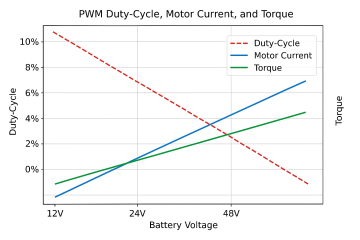
Oh, and I almost forgot, regarding the lower voltage and higher torque, I actually asked ChatGPT about that, and it gave me a diagram, which is how I came to that conclusion.
file_00000000966471f4b02b2c7431e77afa.png

At least, thanks a lot for all your responses so far, they’ve already been really helpful. I’d of course be happy to get even more feedback.

I still have a few days of work ahead, and I probably won’t be back home until Thursday evening. We’ll see , maybe then I can show you how I’m imagining the enclosure and the cable feedthroughs.
 
The smaller signal wires are more challenging due to their size, but maybe there are sealed connectors that can be fully potted
There is many sealed connectors available, but cheap solution is to have a single multiconductor cable pass through a cable gland in order to keep the case waterproof.
Would a XT90 anti-spark connector be sufficient
Can or can't not. Depend of the ESC.
Small models with small capacitor banks will work, but not so well for the larger one.
Manual precharge is quite easy and can be a simple solution.
What type of fuse would be suitable for this kind of high-current setup
High current? 45A continuous and 90A peak. That not high current 😜
It will depend of the size of your battery because a 50 kWh battery don't need the safe fuse as a 5 kWh battery.
If your battery is small, you can look at affordable and compact Eaton Bussmann AMX.
 
I assumed that the heat source and the heatsink would need to be electrically isolated from each other, which is why I considered using a thermal pad. If that’s not necessary, I can of course leave the pad out, I just assumed electrical isolation was required there
If it helps, anodizing provides electrical insulation, if that's required, as long as the anodizing remains intact at all contact points. It is usually so thin that it does not appreciably alter thermal transfer.


If you're just connecting a new heatsink to an existing one, there's no isolation needed, if the existing heatsink wasn't electrically active.


Keep in mind that whatever you use to connect the two items together is going to electrically connect them, too, unless it is a non-conducting material. Most of the non conducting screws, bolts, etc are likely to deform enough under heat to allow shifting or loosening of the thermal mating surfaces, so something that clamps around the entire thing is usualy used instead. If you look inside a common "ebike" controller of some SMPS power supplies or chargers with metal cases, you'll sometimes see a metal bar in front of all the FETs across their plastic surfaces, with threaded holes in between groups of fets, and screws form the outside of the case into that bar to clamp them together. That's one way to do this kind of thing. Soemtimes they'll just use plastic "tophat" washers that fit into the holes in the FETs to keep the screws holding hte FETs to the heatsink from touching the FET electrically active parts, but these can deform over time under enough pressure, and allow the thermal connection to degrade (usually they don't allow electrical shorts, thankfully).
 
Back
Top