7go ebike, wont start

gidi1212

10 mW
Joined
Dec 11, 2024
Messages
20
Location
Gidi1212
E-bike Issue After Short Circuit – Need Help

Dear forum members,

I’m experiencing an issue with my 7GO EB2 e-bike after a short circuit caused by the front light. Since then, the system no longer powers on. I’ve already replaced the following components:

  • The controller (specs and name included in the attached picture)
  • The wiring harness
  • The display (model: NC-81F)
Despite these replacements, the issue persists: the display still won’t turn on. The battery seems to be fine, as I can measure voltage using a voltmeter.

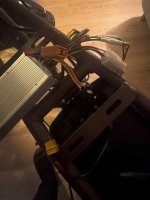
I’ve attached some pictures of the current setup, including the wiring, controller, and the relevant specs of the new controller:
(Pictures attached)

Has anyone encountered a similar issue with the 7GO EB2 or have any ideas about what else I should check? Any suggestions are greatly appreciated!

Thank you in advance!
 

Attachments

  • IMG_2683.jpg
    IMG_2683.jpg
    489.5 KB · Views: 15
  • IMG_2684.jpg
    IMG_2684.jpg
    981.3 KB · Views: 15
  • IMG_2685.jpg
    IMG_2685.jpg
    924 KB · Views: 15
  • IMG_2686.jpg
    IMG_2686.jpg
    453.1 KB · Views: 14
Replaced the controller, harness, and display? Well, there's nothing left, Does the display power on? You should have been able to lay these components out on a table, connected them up to a battery and the display powered up.

What to do next depends on whether the display powered up and bike didn't run or whether it's black, Which is it?

By the way, your bike has some nice video ads, Looks like fun,
Thank you for your response :), it was really really fun when it worked, but no unfortunatly when I lay everything out on a table it does not work, the display does not turn on.
 
LCD displays only need battery power on two pins to turn on. They don't require a working controller. If your display doesn't power up, it's either defective or your aren't getting power to it thru the harness. With a brand new harness, new display, controller and your old battery, it ought to power up unless you didn't seat the display connector or the main harness properly,

Does it have a round green connector like this?
P1220414.JPG
 
LCD displays only need battery power on two pins to turn on. They don't require a working controller. If your display doesn't power up, it's either defective or your aren't getting power to it thru the harness. With a brand new harness, new display, controller and your old battery, it ought to power up unless you didn't seat the display connector or the main harness properly,

Does it have a round green connector like this?
View attachment 363113
yess it has the green waterproof connector, and the two arrows on the male and female ends are correctly connected (also the harness to the controller is correctly connected), so you think it I got a deffective display? can I try it with another 48v display even tho it has a different protocol?
 
With only the battery connected to the controller, measure the voltage of the red conductor of the display connector to ground and confirm that you get a battery level voltage reading.
I cant messure the display connector because the wiring harness imidiatly connects to a waterproof connector that comes uit of the controller
 
Yes, you can test the harness with another display that has the green 5 pin connector. The pin out seems to be universal.

But you can just test the pins directly. It should be a 5 pin female connector coming from the harness. If you're careful, you can put in some wires and check for battery power on the red-to=black without blowing things up. Be careful because that;s your full battery voltage there,

Edit: The display is not connected during this test. All you're checking is if battery power comes thru the harness,

jumper3.jpg

EDi
 
Last edited:
Yes, you can test the harness with another display that has the green 5 pin connector. The pin out seems to be universal.

But you can just test the pins directly. It should be a 5 pin female connector coming from the harness. If you're careful, you can put in some wires and check for battery power on the red-to=black without blowing things up. Be careful because that;s your full battery voltage there,

Edit: The display is not connected during this test. All you're checking is if battery power comes thru the harness,

View attachment 363119

EDi
Update on Testing the Display and Connector

Thank you for the suggestion to test the harness and pins. I’ve already tried using another 36V/48V e-bike display with the same green 5-pin connector. This display works perfectly on another e-bike but not on this one.

To test for power directly, I carefully inserted two copper wires into the green connector—one into the red pin and one into the black pin. The wires did not touch each other, but I did see a small spark briefly. After this, I measured with a voltmeter to the copper wires, but I couldn’t detect any voltage at all.
 
I measured the battery voltage directly and it shows around 50V on the voltmeter.
I did another test using my old controller (i only connected te old controller nothing else to the battery), which has a built-in alarm. When I connected the old controller to the battery and turned it on, the alarm started beeping, which means the battery is definitely providing power.
 
I get the same results as my new controller
I also measured the new controller (with the new harness) using the modified voltmeter. However, the voltmeter does not detect any voltage in the green female connector coming from the harness. It does, however, detect voltage in another non-waterproof connector that comes from the controller.
 

Attachments

  • IMG_2857.jpg
    IMG_2857.jpg
    1.7 MB · Views: 4
I also measured the new controller (with the new harness) using the modified voltmeter. However, the voltmeter does not detect any voltage in the green female connector coming from the harness.
Unplug the battery. Wait for the caps to dissipate or short the black and red battery input connector if you’re in a hurry.
Check for continuity between the red conductor of the controller battery input and the red conductor of the green display connector. If there is no continuity, check the other conductors of the green connector and the red battery input.

IMG_0448.jpeg
 
Last edited:
Unplug the battery. Wait for the caps to dissipate or short the black and red battery input connector if you’re in a hurry.
Check for continuity between the red conductor of the controller battery input and the red conductor of the green display connector. If there is no continuity, check the other conductors of the green connector and the red battery input.

View attachment 363220
When performing a continuity test, I noticed that the multimeter reading changed from 1 (no connection) to around -73 when I connected the two probes: one to the red wire from the battery connector and the other to the red wire from the display connector.
 
What does your continuity test show red probe direct to black probe? That's what you want to see from the red battery lead to the red pin on the handlebar harness.
When I perform the continuity test and connect the two probes directly to each other, the reading fluctuates constantly between +1 and around 150. It doesn’t stay stable at a single value.
 
Back
Top