a DC-DC to charge li-ion... GREAT!!

Doctorbass

100 GW
Joined
Apr 8, 2007
Messages
7,499
Location
Quebec, Canada East
Why DC-DC (like the Artesyn) are perfect for charging li-ion like the A123


The idea with the Artesyn, (Vicor, Lambda, or any other brands ) DC-DC converter is that from the same big power source, you can get many lower and divided voltages that are independent and isolated. They are very compact and small and easy to use. It's like having many single cells charger, but with alot more power than others availlable on the known market like only 2A. They are adjustable and can charge at 4.2V or 3.7V for any chemistry li-ion depending on how you adjust their voltage output. generally they are fully protected and will recover automaticly in a second if shorted. they are very stable and efficient. the artesyn i plan to use the BXB150 serie is 84% efficient! so for cahrging 30A per parallel group i will only dissipate 17.7W. Let say
212W of heat for a 1330W charging!!

After reading alot of comments about BMS and article about the charge of many li-ion string cells, i made my own conclusion since i plan to regulary use my ebike and that i dont want some complications when charging:

-Charge them individually with multiple isolated sources.. forget the cell balance with only one big charger and a balancer.. that's to complicate and the balancer usually balance at max 250 or 500mA so if we want to charge a packs with many serie/parallel cells at current alot higher than 500mA, like 10 or 30A, the balancer will not do the job correctly and will not be able to follow the charge and balance efficiently at the same time!...some circuit like in the dewalt pack, reduce the charge current if one cell goes at higher voltage .. but the charge time increase alot!..

By charging each cells with a charger that will top each of those A123 at 3.7V, i'm sure that no cell will overcharge and that they will be perfectly balanced. The only protection circuit that i will need is a LVC to cutt the controller when the lower cell will reach the 2.7V level...

Seriously, spending 120$ + few buck for the main transfo and activation of the dc-dc circuit.. let say 200$ total for a 12s perfect charger up to 30A !!! i conclude that this is the BEST way to get the maximum performance of the A123 for the use we need! :wink:

Doc
 
Doctorbass said:
Why DC-DC (like the Artesyn) are perfect for charging li-ion like the A123


The idea with the Artesyn, (Vicor, Lambda, or any other brands ) DC-DC converter is that from the same big power source, you can get many lower and divided voltages that are independent and isolated. They are very compact and small and easy to use. It's like having many single cells charger, but with alot more power than others availlable on the known market like only 2A. They are adjustable and can charge at 4.2V or 3.7V for any chemistry li-ion depending on how you adjust their voltage output. generally they are fully protected and will recover automaticly in a second if shorted. they are very stable and efficient. the artesyn i plan to use the BXB150 serie is 84% efficient! so for cahrging 30A per parallel group i will only dissipate 17.7W. Let say
212W of heat for a 1330W charging!!

After reading alot of comments about BMS and article about the charge of many li-ion string cells, i made my own conclusion since i plan to regulary use my ebike and that i dont want some complications when charging:

-Charge them individually with multiple isolated sources.. forget the cell balance with only one big charger and a balancer.. that's to complicate and the balancer usually balance at max 250 or 500mA so if we want to charge a packs with many serie/parallel cells at current alot higher than 500mA, like 10 or 30A, the balancer will not do the job correctly and will not be able to follow the charge and balance efficiently at the same time!...some circuit like in the dewalt pack, reduce the charge current if one cell goes at higher voltage .. but the charge time increase alot!..

By charging each cells with a charger that will top each of those A123 at 3.7V, i'm sure that no cell will overcharge and that they will be perfectly balanced. The only protection circuit that i will need is a LVC to cutt the controller when the lower cell will reach the 2.7V level...

Seriously, spending 120$ + few buck for the main transfo and activation of the dc-dc circuit.. let say 200$ total for a 12s perfect charger up to 30A !!! i conclude that this is the BEST way to get the maximum performance of the A123 for the use we need! :wink:
Doc

Hey Doc

Could you please elaborate further on this new method you have discovered; Could i apply this to a 100v a123 setup? i'd be really interested in doing this as per i'm looking for a charging setup.

thanks
Steveo
 
steveo said:
Doctorbass said:
Why DC-DC (like the Artesyn) are perfect for charging li-ion like the A123


The idea with the Artesyn, (Vicor, Lambda, or any other brands ) DC-DC converter is that from the same big power source, you can get many lower and divided voltages that are independent and isolated. They are very compact and small and easy to use. It's like having many single cells charger, but with alot more power than others availlable on the known market like only 2A. They are adjustable and can charge at 4.2V or 3.7V for any chemistry li-ion depending on how you adjust their voltage output. generally they are fully protected and will recover automaticly in a second if shorted. they are very stable and efficient. the artesyn i plan to use the BXB150 serie is 84% efficient! so for cahrging 30A per parallel group i will only dissipate 17.7W. Let say
212W of heat for a 1330W charging!!

After reading alot of comments about BMS and article about the charge of many li-ion string cells, i made my own conclusion since i plan to regulary use my ebike and that i dont want some complications when charging:

-Charge them individually with multiple isolated sources.. forget the cell balance with only one big charger and a balancer.. that's to complicate and the balancer usually balance at max 250 or 500mA so if we want to charge a packs with many serie/parallel cells at current alot higher than 500mA, like 10 or 30A, the balancer will not do the job correctly and will not be able to follow the charge and balance efficiently at the same time!...some circuit like in the dewalt pack, reduce the charge current if one cell goes at higher voltage .. but the charge time increase alot!..

By charging each cells with a charger that will top each of those A123 at 3.7V, i'm sure that no cell will overcharge and that they will be perfectly balanced. The only protection circuit that i will need is a LVC to cutt the controller when the lower cell will reach the 2.7V level...

Seriously, spending 120$ + few buck for the main transfo and activation of the dc-dc circuit.. let say 200$ total for a 12s perfect charger up to 30A !!! i conclude that this is the BEST way to get the maximum performance of the A123 for the use we need! :wink:
Doc

Hey Doc

Could you please elaborate further on this new method you have discovered; Could i apply this to a 100v a123 setup? i'd be really interested in doing this as per i'm looking for a charging setup.

thanks
Steveo

You could use this method to charge up to 1500V... thatis the isolation between input and output of these converters. No problem with 100V!

There are no real limitation about this new method. the limiting factor would be the max power you can have at the input. In case of dc-dc that have a 36 to 75V dc input, you need a power supply capable of delivering that voltage and power you would like to have at output +16%.
(84% that is the efficiency of these modules) so you absolutly need the dc-dc converter plus a power supply. the dc=dc only transform the voltage and isolate the power supply to allow you to connect each unit in serie without shorting between each string cell.

Theorically with DC-DC converter, you can charge any number of cells up to the isolation voltage of the dc-dc you have !.

This is a very versatile method at raisonnable cost!
 
Doctorbass said:
steveo said:
Doctorbass said:
Why DC-DC (like the Artesyn) are perfect for charging li-ion like the A123


The idea with the Artesyn, (Vicor, Lambda, or any other brands ) DC-DC converter is that from the same big power source, you can get many lower and divided voltages that are independent and isolated. They are very compact and small and easy to use. It's like having many single cells charger, but with alot more power than others availlable on the known market like only 2A. They are adjustable and can charge at 4.2V or 3.7V for any chemistry li-ion depending on how you adjust their voltage output. generally they are fully protected and will recover automaticly in a second if shorted. they are very stable and efficient. the artesyn i plan to use the BXB150 serie is 84% efficient! so for cahrging 30A per parallel group i will only dissipate 17.7W. Let say
212W of heat for a 1330W charging!!

After reading alot of comments about BMS and article about the charge of many li-ion string cells, i made my own conclusion since i plan to regulary use my ebike and that i dont want some complications when charging:

-Charge them individually with multiple isolated sources.. forget the cell balance with only one big charger and a balancer.. that's to complicate and the balancer usually balance at max 250 or 500mA so if we want to charge a packs with many serie/parallel cells at current alot higher than 500mA, like 10 or 30A, the balancer will not do the job correctly and will not be able to follow the charge and balance efficiently at the same time!...some circuit like in the dewalt pack, reduce the charge current if one cell goes at higher voltage .. but the charge time increase alot!..

By charging each cells with a charger that will top each of those A123 at 3.7V, i'm sure that no cell will overcharge and that they will be perfectly balanced. The only protection circuit that i will need is a LVC to cutt the controller when the lower cell will reach the 2.7V level...

Seriously, spending 120$ + few buck for the main transfo and activation of the dc-dc circuit.. let say 200$ total for a 12s perfect charger up to 30A !!! i conclude that this is the BEST way to get the maximum performance of the A123 for the use we need! :wink:
Doc
Hey Doc

Could you please elaborate further on this new method you have discovered; Could i apply this to a 100v a123 setup? i'd be really interested in doing this as per i'm looking for a charging setup.

thanks
Steveo

You could use this method to charge up to 1500V... thatis the isolation between input and output of these converters. No problem with 100V!

There are no real limitation about this new method. the limiting factor would be the max power you can have at the input. In case of dc-dc that have a 36 to 75V dc input, you need a power supply capable of delivering that voltage and power you would like to have at output +16%.
(84% that is the efficiency of these modules) so you absolutly need the dc-dc converter plus a power supply. the dc=dc only transform the voltage and isolate the power supply to allow you to connect each unit in serie without shorting between each string cell.

Theorically with DC-DC converter, you can charge any number of cells up to the isolation voltage of the dc-dc you have !.

This is a very versatile method at raisonnable cost!

sounds like a method i would absolutly like to try :D

how do i adjust the voltage thou? you said it could be adjusted from 4.2v output max down to 3.7v correct? is there a pot to do this?

can this method charge a123/lipo/lith-ion?;

What transformer would i need to use? 120ac to say 36 - 72v dc right? how about for the amps?.. i'll be c

if i'd like to do a 100v charger; therefore i would need 30 of these units correct..

thanks
Steveo
 
- Output voltage is adjusted using external resistors between pins 7 and 8 for higher and between pins 6 and 7 for lower. See the data sheet.
Not sure of the values yet but we'll work that out no prob.
Voltage can vary between 60% to 110% of nominal 5V (also on data sheet), so thats 5.5V max to 3V min, could be done with a pot but may be more stable with a resistor.

- If you want to charge lipo/lith-ion or 'low C' LiFePO4 you'll have to make sure you've got enough Ah (Amp hours) in each parallel group to keep within their limited C rating. So for a 1C battery chemistry that means 30Ah per // group. For 2C it'll be 15Ah. If you don't then you could have a fire on your hands or worse. :!:

- You'll need some DC power supplies, possibly like this one or this. I hope these can be paralleled together to increase the available current to the converters.

- If you want a 100V set-up then firstly I strongly suggest you get very familiar with how electricity and electronics work; so much so that you could answer these questions yourself easily. I don't want to discourage you, far from it, it's just that 100V DC can be seriously LETHAL :!: and since it's DC you stick to it while you fry. :shock: 30 converters is right for a 100V charger but you won't be able to just plug it in to any US socket unless your power supplies limit the current to the converters. At full power 30 of these will draw 30 x 150 W= 4.5kW!! Add in inefficiencies in the power supplies and converters and that'll be more like 5kW. You could split the pack into sub packs and charge each one on a different mains circuit but I'll let you figure out how to do that. :wink:
 

Hi Doc:

I agree that you have a great idea, but I think you're talking about using a LOT of amps. For example, if you have a 20s 6p pack, each sub-pack would have about 14ah, and could be charged at 28 amps for a 2C charge rate. So to charge all 20 sub-packs, you'd need 560 amps @ 3.7v (ideal). Since the dc-dc converters are 84% efficient, you'd really need about 670 amps. That's about 2500 watts.

If you can get that type of power, and they don't overheat, you'd really be in business. You'd be able to charge your bike in about 40 minutes (my guess).

Also, each converter will dissapate about 15w of heat during charging. I'd check to be sure that they can handle that.

The charger you're talking about would be about as powerful as a clothes dryer or oven etc. I think its the direction we need to go.

However, I think the ideal solution would use a single 3.7v power supply that uses the isolating circuitry similar to the dc-dc converters you're talking about. Unfortunately, I don't know how to make it.

Please keep me posted. I think you may be onto something really good.

Have you tried this set-up yet?

 
The price of the DC/DC converters Doc and I bought was about a tenth of their list price on digikey. Does any one have any info on the cost of similar converters? When I've googled for them I can't seem to find any sites that list a price directly.

Theebay site where I bought mine quoted me $11.50 each for 100. Is there anyone in the UK who wants to put together a group buy?

I hope we'll still be able to get these at this price in the future. Any info about the future availability of these or similar converters would be very useful.

Anyone got any ideas why these are so cheap?
 
The difficulty is going to be supplying these things with power. Aparently they can handle 150 watts, so that isn't a problem. However, if you want to charge at 150w (or 120 watts @ 3.7v), you'll have to supply them with about 5 amps @ 60v. If you're planning on running 20 of these, you'll need 100 amps @ 60v. That's a HUGE power supply. I haven't seen anything like that available except for $3000 etc. Also, you'd need a big 220v circuit for it. You'd most likely have to resort to using five 60v, 20 amp supplies instead.

Doc, how do you plan to power these things?

 
I can see that reading this tread, begin to discovere the advantages of isolated DC-DC !

There is an importang thing that i want to clarify now about thtse artesyn modules.

They are CAPABLE of output 150W or 30A.. but this isn't the only goal... you can yse them to a lower current too! they have a voltage sens that will control the output so if you use these feedback input to vary the current that should work.

I'm just trying to explain to all of you that they can handle up to 30A.. but they can be used at a lower current output too! if you give them 25W at the input, they will never exceed 22W at output.. you see?

the big number 150W....30A are impresive, but it is more to indicate you that they are robust !

Alot of people here would like to get more than the 2A availlable from the voltfreak charger. I think that these dc-dc are a good solution. Remember that the advantage is that you can adapt these modules into any li-ion voltages with two simples resistors that cost you less than 1cents.....

Let say you already have a 20A 40V power supply. That's 800W. with 800W and the 84% efficiency of the modules that's 672W. To charge a 20s pack that's 33.6W per parallel cell group... and charging to 1C would mean 4 cells.. so 20s4p would be cahrged in 1hour with that ! an dyou will need to dissipate 128W of heat.. an old computer case with fan could have enough metal surface and air flow to do the job very fine!

Doc
 
Power it with deep cycle lead. Then you could charge up faster than 40 minutes.

Use whatever cheap trickle charger to get your lead bank charged up at your leisure. Or charge the lead with a few HF $200 solar arrays if you're so inclined.
 
Beagle123 said:
The difficulty is going to be supplying these things with power. Aparently they can handle 150 watts, so that isn't a problem. However, if you want to charge at 150w (or 120 watts @ 3.7v), you'll have to supply them with about 5 amps @ 60v. If you're planning on running 20 of these, you'll need 100 amps @ 60v. That's a HUGE power supply. I haven't seen anything like that available except for $3000 etc. Also, you'd need a big 220v circuit for it. You'd most likely have to resort to using five 60v, 20 amp supplies instead.

Doc, how do you plan to power these things?


Since it's DC, could they not just put them in parallel with some diodes coming out of each to help prevent some back flow of current? It would be a little messy setup, but with some beefy enough cables should be able to handle it.
 
Beagle123 said:
How are you guys planning on powering these things?

Pretty simple; as a first thought, rewind the output transformer of a 400W PC power supply to supply 48V, then tie all of the inputs of the 15 DC/DC converters in parallel and wire to the modified PSU.

The output voltage setting is only 1% tolerance, I'd want better than that, I think, in order to maximize battery cycle life careful trimming of the output with resistors should achieve that.

Alternatively, charge to, say, 3.7V/3.65V then a simple - but precise - clamp circuit to 3.65V/3.6V to ensure balance before going under load might suffice.

It is rather a pity that none of the semiconductor manufacturers have yet introduced a single-chip Li charge CCCV controller for LiFePO4 chemistry, the only ones I have found are for conventional chemistry with a 4.1 or so cut off.
 
So if you use a 400 watt power supply for 20 batteries, you'll be getting about 20 watts for each cell (minus losses). You could probibly charge in a couple of hours.

Please keep me updated. I'd like to see it.

 
Doc,
How hot do those things get?

Since they are fairly small, in some cases it might be cool to build them into the battery pack itself so you just need to carry a simple 48v SMPS around for charging. This would eliminate a huge pile of spaghetti wires at the charger connection too. Nice simple two wire plug.

I'd have to scratch my head a while to figure out how you would use the voltage trim to control the current. If there was a way to limit the current based on the input voltage, then if you used a smaller 48v supply, it would automatically charge at the highest rate it could based on the available current.

An even smaller version of those might be cool.


I wonder what would happen if you put the input of two or three in series? You might be able to power it through a bridge rectifier directly from the AC line :twisted:
 
Ggoodrum should receive them on december 17. he help me about by being e relay for the shipping... the seeler wanted to sell only in the US so Ggoodrum will re ship the package to me.

fechter said:
I wonder what would happen if you put the input of two or three in series? You might be able to power it through a bridge rectifier directly from the AC line :twisted:

The only problem with that method is that if one of the 3 in serie is a bigger load, thethe will not be balanced .. some will receive 30V , some 40 and maybe 50V.... ro get good results with 3 wired in serie, the load of each should be the exact same.. the lower input voltage(the higher load of the 3 unit) would shut down if it drop under the 35V min limit input...

But i agree that directly using the 120Ac would be great... but i have a big toroidal transformer of 1.2kW with 2 x 60V 10A.. i will split the secondary into 3 x 40V 15A = 40Vac at 45A..... = 56V DC no load at and maybe 50V at 45A that will be great to supply all the 12 DC-DC...

Also, one of my good friend gaved me 2x 12V 42A server power supply!

I have 24V at 42A or 12V at 84A... They are brand new.. apparently they wanted to but them in the garbadge!!!

Also, at my job, today, a department cleaned their lab from old stuff that only take dust from 5 years+.. and they had a couple of box full of electronic component from old and abandoned project... transfo, vicor power supply., connector, capacitor, great mylar capacitors, 1/0 gauge wires.. etc.. wow!.. i toke all them 8)

I will only need to put them in my lab and garage and to let my girlfriend accept that... :lol:

Doc
 
Update 22 dec 2007:

I got a couple of box of electronic stuff at my job this week.

Again.. totally free... :D I have really good plugs!

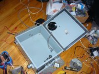
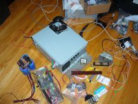
I got the box i will use to enclose my charger. A beautifull industrial grade steel case with a 5" fan on it. (See pics below)

While i have been waiting to receive my Artesyn module from the relay shipping of GGoodrum (he doesn't charged me for the shipping (THANKS GARY!) :mrgreen: .. like a christmass gift... :wink: I began to desing and did some test with the first stage of the power supply.

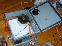
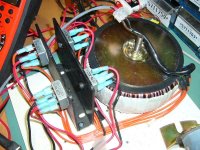
I'm testing the thermal conductivity of each part for the heat sinking of the bridge rectifier, transfo, resistor..etc my 1000VA toroidal transformer that i modified to have 4 x 30Vac rms at 8.3A will be coupled to 4x 35A bridge rectifier (KBPC35-06) and the DC output will goes to one big 100000uF 50V capacitor.

I should get less than 10% ripple at the input of the Artesyn modules.

All the component will have to be a little squeezed into that box. the big transfo need 6.5" dia, the Artesyn DC-DC will dissipate around 200W with the charger at full power (750W out), the bridge rectifier will dissopate around 10W each (40 total) and the transfo 25W.. for a total of 265W of heat to diffipate with alot of heat sink plate with fines and the great work of the 5"fan of 22W... a it's like hearing a real turbine with its metal blade!!

Transfo: 6.5" dia of space required
Capacitor: 3" dia of space required
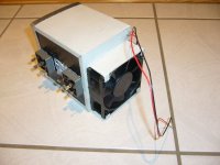
Bridge rectifier + heat sink: unknow exactly from now.. maybe i will use my module combo that i've previously built for another project... it's a heatsink tunel folded with a 3" fan... it take alot of place but is very cooling efficient! (see pics below)

Ideally i would like to use only une "L" plate to sink the 4 rectifier but the temperature jonction of the diodes will reach a dangerous state of 110 degree C with convection colling wich is not very acceptable.. I will measure what can i get with the same L plate into the fan cooled case.

I hope i will get good results !

This 750W output Universal Li-ion Cell Charger/balancer seems to take a little bit more time to built !!.. i've never imagined that i would need to calculate the heat dissipation at this state!

Now i can observe that the L plate is at 46 degree C with one 35A bridge rectifier on it while driving 6A and 212Watts...

More developpment to come!


Doc
 

Attachments

  • P1030606_800x600.jpg
    P1030606_800x600.jpg
    112.9 KB · Views: 6,651
  • P1030607_800x600.jpg
    P1030607_800x600.jpg
    123.9 KB · Views: 6,660
  • P1030608_800x600.jpg
    P1030608_800x600.jpg
    109.6 KB · Views: 6,665
  • P1030610_800x600.jpg
    P1030610_800x600.jpg
    59.8 KB · Views: 6,665
  • P1030611_800x600.jpg
    P1030611_800x600.jpg
    95.4 KB · Views: 6,670
Wow! that's some heavy duty hardware there, doc.

That should do the job. Nice cooling system.

Kinda makes you wonder if you could make a switching power supply with the same rating? It would weigh less :wink:

I forget, how many amps are you building this for?
 
Theoricaly, i would be able to charge each 3.6V group to 18.1A that is equal to 65.3W per parallel group.

I just finished to install the 4 bridge rectifier and the 100000uF capacitor and i tested the output and the ripple.

With many paralleled load, i acheived around 980W of output (30.2A at 32.4V)
If i decrease the load, i also tested with 552W(36.3V at 15.2A). the volt decrease du to the non regulated state and some resistance of the 16 gauge wire i choosed for each of the 4 secondary output. The 16 gauge act as a damper when i start the transformer. The bridge rectifoer have to fully charge the capacitor from zero V with its very low resistance...I dont want that the very peak high current to blow the diodes...

I have 12 Artesyn DC-DC modules to supply so i will have 2.52A for each DC-DC input (that are rated 6.5Amax). that is 81.6W input for each one. They are rated 84% efficient.. but it' is at 48V input... so i will be conservative and assube that it will be around 80%. 81.6 x 0.8 =65.3W out. x 12 = total of 783W.

With that i hope to be able to recharge my future(i progress) 2000Wh battery pack in less than 3h :mrgreen:

Doc
 

Attachments

  • P1030614_800x600.jpg
    P1030614_800x600.jpg
    124.1 KB · Views: 6,615
I know I some 48v nominal DC-DC converters I have right now give their specs as browning out at 32v dc input. They say 75% output at the 32v input. Just something to check out.
 
magudaman said:
I know I some 48v nominal DC-DC converters I have right now give their specs as browning out at 32v dc input. They say 75% output at the 32v input. Just something to check out.


Thanks for that info.

I dont have the efficiency graph of my artesyn now, but they specify 84% eff at full output at 48V. I will endure that my heatsink cluster for the 12 artesyn modules inside the case will be enough large to dissipate all the heat with the 5" cooling fan.

I'm still waiting to receive my artesyn module in the next days.

Doc
 
Update 28 dec 2007

I just received this afternoon my Dc-DC Artesyn modules relay shipped by Gary :mrgreen:

I will begin to mount those and test those soon. And let you know the resusts!
i toke some pics for you :
:mrgreen:
 
Back
Top