a DC-DC to charge li-ion... GREAT!!

Doctorbass said:
efreak said:
I had bought one before this... but when emailing vendor regardin g shipping to great white north ; he was asking how many i needed which led me to believe there are more . so far payment gone through by rights should get it within a week i hope and if we need a circuit then DOC .... you know you will be even more popular than you are now

( autograph ??)

Searching over the internet for the original's doc autograph of the BTTF, look what i've found!!

They are suposed to be availlable since the month of may!!!

I NEED ONE

http://www.actionfigureinsider.com/main/?p=565


Doc


That'll take you back to University for sure ..... maybe even high school :p
 
Hi, I'm the guy that picked up the eltek. I've been using this method of charging for several years without any problems and found this forum a while ago - sorry I haven't had time to contribute - though most of what I would has already been! I'll be using this to power 8 DC converters wired directly to 200AH LiFePO4 cells on my electric boat, should charge them up pretty quick ;)

I will be bummed if I can't power it up directly, but I don't think it's likely.
z.
 
Welcome to the forum PowerMed,

What an impressive stable of electric toys and very nice boat to boot!


yes i sure hope that it is not imposible to get power thru the flatpack.

what kind of converters do you use and how many and what about a circuit for adjusting the voltage output how does that all go?
 
I use individual, small but very beefy dc converters - solid state Vicors trimmed to exactly 3.65 v with a single resistor, capable of putting out around a maximum of 80 amps - way out of ebike territory! You have to be careful to match your batteries, power supply (house and AC to DC), and dc converters to get it right.

One advantage of such a powerful setup and fast charging times is I can set everything up on a timer - and use my cell phone alarm as a backup - to make sure and turn it completely off pretty soon after I'm home and packed away. For long term / very low current / constant voltage I simply power the string with a 25.6 v power supply rigged from a small Kensington notebook adapter (they are pretty easy to modify to any current from zero to around 8 amps and from zero to a max of 26 volts - cut off the cable at one end and 2 small trim pots on the small wires does it). I can leave that on it forever if I need to. You can pick them up on ebay for as low as $10.
 
ok i have my first power supply meanwell 48v 500wat out put 8.4 amps at 48volts when running on 110 volts after i try attaching my first module to it realized duh 2.4 amps max input 36-72 volt... i am hoping that is just over current protection circuit and the module is itself ok . first bit my own firworks with more to come i am sure ( hopefully none too costly)

for testing purposes how can i run one module that requires only 2.4 amps to run on this meanwell power supply that supplies 8.4 run a something in parallel that eats the rest amps like 2 more modules?? for 7.5 or 7.2 amp load supply 8.4 amps??
 
efreak said:
ok i have my first power supply meanwell 48v 500wat out put 8.4 amps at 48volts when running on 110 volts after i try attaching my first module to it realized duh 2.4 amps max input 36-72 volt... i am hoping that is just over current protection circuit and the module is itself ok . first bit my own firworks with more to come i am sure ( hopefully none too costly)

for testing purposes how can i run one module that requires only 2.4 amps to run on this meanwell power supply that supplies 8.4 run a something in parallel that eats the rest amps like 2 more modules?? for 7.5 or 7.2 amp load supply 8.4 amps??

Your Meanwell power supply CAN run probably up to 10.4A.. in your case maybe 8.4.. but it is not a NEED to output 8.4A... that depend on the load you apply on it.

for exemple. a simple DC-DC that take 75W at the input will need 90W/48V = 1.87A... no more...

the current that travel thru a circuit is dependent on the load... often compared to a simple resistor.

ex: Current = Voltage / Resistor

In your case, if you draw 2.4A at 48V, your DC-dc is like a load resistor of R=V/I = 48/2.4 = 20ohms

About the 2.4A protection, they mean that at the lowest voltage you can apply on it to oprerate correctly is something like 36V.. the more voltage you apply on it, the less current it will need. so at a lower voltage, like the minimal, it should normally draw more current..and could reach the max value of 2.4A sooner than at if operating it at 72V.

so 36V at 2.4A = 86.4W.

That mean that if you operate it at 36V and that you draw more than 84W , it may enter in protection mode and will shutdown and restart and pulsate even if the load is removed.

In your case, you have 48V so at 2.4A it's 115.2W at the input of the DC-DC.. supposing that it is 80% efficient, that's 92.2W at the output.

With a cell of 3.6V it's a max current of 25.6A and for the lipo, (4.2V) it's 22A max.

Doc
 
Thanks a lot Doc that is very helpful

What I was trying to do ; I hooked up just one module to power supply to see if it will output 3.3 volts but some sparks and high pitched noise eminating module but no reading on the output.

do i have to apply load to get a reading i got worried to see the spark as well as the high picth noise and heat in the one spot where they say it is for heat measurment.

so i should be able to test with one module hookd up or do i need to hook up 4 at a time i want to be sure before hand .

thanks again
 
i'll post a video of How to use a DC-DC for charging a li-ion cel soon :wink:

Doc
 
that would be so very helpful


Much appreciated
 
Not yet, but I'll be glad to give a first hand report when it arrives. In reviewing the units I found nothing indicating that there would be a problem. They look good on paper - considerng output wattage per pound (confirmed by efficiency ratings) they're the most efficient of all the units on ebay I found. Proofs in the pudding...
 
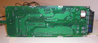
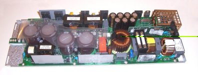
I got mine yesterday. Here's the insides.View attachment 3underside.jpgsideview.jpg

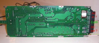
I found continuity between each of the two groups of pins marked L (for live, as shown in underside.jpg) and one each of the fuses (shown in topside.jpg) but each fuse is isolated from each other. The center underside pins are Earth. The other two groups of pins are, I assume, Neutral for the mains input. I'm not sure why there would be two seperate lines for live and neutral input. I rather cheekily called Eltek tech support and asked them but the guy there didn't want to give too much away, as I'm not a direct customer, but he did confirm that they are inputs on the underside of the PCB but couldn't (wouldn't) confirm that both needed to be connected at the same time of if any damage would ensue if they were. The three pins at the center on the top of the PCB go to three small spade connectors and there are a bunch of pins on either side which are difficult to access due to the plastic connector casing.

underside2.jpg
Edit: Sorta forget what's written above. :oops: I found continuity between the outermost group of pins marked 'DC out' shown in underside2.jpg and the shunt so I'm assuming that's +V DC out they are also connected to the pins above them on the top side of the PCB. The group of pins next to these are connected top and bottom of the PCB but not to the shunt (therefore -V DC out?) The two groups of pins near the large inductor which comes through the PCB are AC in maybe? would both be protected by fuses?

Any advice/observations would be appreciated before I put 240VAC through it. Thanks.
 
48V 32A

http://cgi.ebay.com/Meanwell-RSP-1500-48-48V-32A-DC-Switching-Power-Supply_W0QQitemZ320266476471QQihZ011QQcategoryZ58288QQssPageNameZWDVWQQrdZ1QQcmdZViewItem
 
frodus said:
48V 32A

http://cgi.ebay.com/Meanwell-RSP-1500-48-48V-32A-DC-Switching-Power-Supply_W0QQitemZ320266476471QQihZ011QQcategoryZ58288QQssPageNameZWDVWQQrdZ1QQcmdZViewItem

:shock:

I take it!!!

Thankd Frodus!!!

That's what i need to charge 15A 12s 4.2V !! using my DC-DC configuration!!

Does anyone help me to buy it from the US for relay shipping to canada??? :mrgreen:
 
flip_normal said:
I got mine yesterday. Here's the insides.View attachment 3View attachment 2View attachment 1

I found continuity between each of the two groups of pins marked L (for live, as shown in underside.jpg) and one each of the fuses (shown in topside.jpg) but each fuse is isolated from each other. The center underside pins are Earth. The other two groups of pins are, I assume, Neutral for the mains input. I'm not sure why there would be two seperate lines for live and neutral input. I rather cheekily called Eltek tech support and asked them but the guy there didn't want to give too much away, as I'm not a direct customer, but he did confirm that they are inputs on the underside of the PCB but couldn't (wouldn't) confirm that both needed to be connected at the same time of if any damage would ensue if they were. The three pins at the center on the top of the PCB go to three small spade connectors and there are a bunch of pins on either side which are difficult to access due to the plastic connector casing.


Edit: Sorta forget what's written above. :oops: I found continuity between the outermost group of pins marked 'DC out' shown in underside2.jpg and the shunt so I'm assuming that's +V DC out they are also connected to the pins above them on the top side of the PCB. The group of pins next to these are connected top and bottom of the PCB but not to the shunt (therefore -V DC out?) The two groups of pins near the large inductor which comes through the PCB are AC in maybe? would both be protected by fuses?

Any advice/observations would be appreciated before I put 240VAC through it. Thanks.

that's great pics!! Thanks Flip!!

I would assume that the large inductor (by directional monocore) is to filter the noise from the main AC line.. and the other side where you indicated DC would be exactly the DC output.. the large caps and diode are very close to that and that proove that the DC is close to this place..

can it work on 120V AC?
 
Doctorbass said:
Does anyone help me to buy it from the US for relay shipping to canada??? :mrgreen:
No problem..PM me. :mrgreen:
 
TylerDurden said:
I don't know if they allow Canadian bidders:

http://cgi.ebay.com/Eltek-Flatpack2-2000W-48V-NEW-4C_W0QQitemZ230262788143QQihZ013QQcategoryZ20315QQssPageNameZWDVWQQrdZ1QQcmdZViewItem


Doc, I will help bid for you if there is any international issue.

I would also like to purchase, so if Doc passes, anybody else in line?

:mrgreen:

Tylker, i think your offer could ve usefull regarding thisone that frodus shown from ebay:
http://cgi.ebay.com/ws/eBayISAPI.dl...Track=true&ssPageName=VIP:Watchlink:middle:us

Doc
 
Doctorbass said:
I would assume that the large inductor (by directional monocore) is to filter the noise from the main AC line.. and the other side where you indicated DC would be exactly the DC output.. the large caps and diode are very close to that and that proove that the DC is close to this place..

can it work on 120V AC?

Yes, 85 - 300 VAC input.

OK hooked that up and hear a click then read 48V DC out then 3 secs later another click and output turns off. :?
 
lots of AC DC switchers have to have a load on them to operate.... put a dummy load on it (like an extra converter with a fuse on it, or a high watt resistor) and try it.

My vicor does that.
 
Oops, me bad again. I didn't have the fans connected, which is why it turned itself off. Now with the fans hooked up it works fine, no load, 53.4V DC out. Thanks for the hint tho' frodus.View attachment underside3.jpg
Happy happy joy joy. Looks like I got me a 2kW 1.9Kg PSU. For $140 delivered. 8)
 
Since I'm waiting for the one I purchased, I'm very, very happy about that...from what I can tell, it's a fantastic unit for delivering big amps to lithium cells. I'll get a picture up when I've assembled mine with the individual converters. How are you planning on shutting off the charge cycle?
 
Back
Top