a DC-DC to charge li-ion... GREAT!!

I'd like to see you measure that 2000W :) I seriously DOUBT you can...

And there's no way you can do that through a normal 120V socket. That 2000W is likely at the 240V input, and at 120V its likely Half that.
 
http://www.eltekvalere.com/photoalbum/view2/P3NpemU9b3JnJmlkPTE0OTI3NCZ0eXBlPTE

2000W 41.7A@48V at nominal input (185-275VAC) which is basically saying you're not gonna see that on a 120VAC input.

look at the datasheet, notice the alarms... fail on fan disconnect.

That thing is cool, canbus :)

do you have a can reader? that'd be cool to interface.
 
frodus said:
I'd like to see you measure that 2000W :) I seriously DOUBT you can...

And there's no way you can do that through a normal 120V socket. That 2000W is likely at the 240V input, and at 120V its likely Half that.

I've got 100 x 10Ah Headway cells arriving in a couple of days...hopefully...bites nails...looks out window and 20 x Artesyn 150W DC/DC converters waiting to charge them up, sitting here ready. :D
Once I've built the batt packs and hooked it all up and checked the amps with a clamp meter, that is!

powermed said:
Since I'm waiting for the one I purchased, I'm very, very happy about that...from what I can tell, it's a fantastic unit for delivering big amps to lithium cells. I'll get a picture up when I've assembled mine with the individual converters. How are you planning on shutting off the charge cycle?

Good Question...scratches head :? :roll:
 
flip_normal said:
frodus said:
I'd like to see you measure that 2000W :) I seriously DOUBT you can...

And there's no way you can do that through a normal 120V socket. That 2000W is likely at the 240V input, and at 120V its likely Half that.

I've got 100 x 10Ah Headway cells arriving in a couple of days...hopefully...bites nails...looks out window and 20 x Artesyn 150W DC/DC converters waiting to charge them up, sitting here ready. :D
Once I've built the batt packs and hooked it all up and checked the amps with a clamp meter, that is!
:roll:

it'l give you 2000W at 240VAC... if you're ok with wiring it to work with the higher voltage. 120V at 12.5A (Max AC input current for this model), is 1500W, and at 90% eff, thats MAYBE 1350W, at 48V... is still 28A... but you won't see that.... not likely.

Just be sure you're not overloading the power supply, if it senses overcurrent, it WILL shut down, or fault. If each converter is 150W on the 48V input side, thats 3.125A roughly, so the most modules you could put on that power supply is... 9 MAX at 120V...

now go to 240V, you could get 13 modules hooked up. at around 41.6A output.

Thats going to be alot of heat though, so keep things cool... 2000W*0.90efficiency is still 200W of loss in heat.
 
frodus said:
it'l give you 2000W at 240VAC... if you're ok with wiring it to work with the higher voltage. 120V at 12.5A (Max AC input current for this model), is 1500W, and at 90% eff, thats MAYBE 1350W, at 48V... is still 28A... but you won't see that.... not likely.

Just be sure you're not overloading the power supply, if it senses overcurrent, it WILL shut down, or fault. If each converter is 150W on the 48V input side, thats 3.125A roughly, so the most modules you could put on that power supply is... 9 MAX at 120V...

now go to 240V, you could get 13 modules hooked up. at around 41.6A output.

Thats going to be alot of heat though, so keep things cool... 2000W*0.90efficiency is still 200W of loss in heat.
240VAC is all we got this side of the pond, 'cept 450V 3 phase :twisted:

I'm gonna do the excellent current limit hack on the Artesyn converters which Docbass worked out earlier in this thread. Re. heat: I'm on the lookout for heatsinks, but kinda run out of cash at the moment.
 
thats good to hear on the 240VAC... perfect for the power supply...

now, when you mod the artesyn, does that increase the input current to the converter? if so, 20 modules @ 3.125A will be too much for that power supply....

you might just make a circuit that does 10 modules at a time, and switches them off, then turns on the others...

if you hit current limit, your PS will keep turning off.

if you NEED to do 20, you might consider getting 2 supplies.
 
IIRC Doc managed to PWM the input side of the DC/DCs so the output current can be adjusted between 37A and 15A at 3.65V so I should be able to adjust the charge current so that the PSU stays on. I'd have liked to have got 2 more of the Flatpack2 PSUs but the cash flow is a bit tight right now.
 
flip_normal said:
Oops, me bad again. I didn't have the fans connected, which is why it turned itself off. Now with the fans hooked up it works fine, no load, 53.4V DC out. Thanks for the hint tho' frodus.View attachment 3
Happy happy joy joy. Looks like I got me a 2kW 1.9Kg PSU. For $140 delivered. 8)

WOW.. that's great to see that it work without any ext parts!! like my ?%&?%$&$ Pionner magnetics!!! :(

I have two 6x DC-DC DIY modules that still wait to be supplied by these monster AC-DC 48V supply!
 

Attachments

  • DSCN4797_1024x768.jpg
    DSCN4797_1024x768.jpg
    117.4 KB · Views: 1,574
  • DSCN4799_1024x768.jpg
    DSCN4799_1024x768.jpg
    73.5 KB · Views: 1,567
  • DSCN4801_1024x768.jpg
    DSCN4801_1024x768.jpg
    148.3 KB · Views: 1,571
Thanks a lot for all of the above folksneedless to say i am Exubrated jumping with joy nice pics too

I feel the need to pay tuition :D
 
frodus said:
flip_normal said:
frodus said:
I'd like to see you measure that 2000W :) I seriously DOUBT you can...

And there's no way you can do that through a normal 120V socket. That 2000W is likely at the 240V input, and at 120V its likely Half that.

I've got 100 x 10Ah Headway cells arriving in a couple of days...hopefully...bites nails...looks out window and 20 x Artesyn 150W DC/DC converters waiting to charge them up, sitting here ready. :D
Once I've built the batt packs and hooked it all up and checked the amps with a clamp meter, that is!
:roll:

it'l give you 2000W at 240VAC... if you're ok with wiring it to work with the higher voltage. 120V at 12.5A (Max AC input current for this model), is 1500W, and at 90% eff, thats MAYBE 1350W, at 48V... is still 28A... but you won't see that.... not likely.

Just be sure you're not overloading the power supply, if it senses overcurrent, it WILL shut down, or fault. If each converter is 150W on the 48V input side, thats 3.125A roughly, so the most modules you could put on that power supply is... 9 MAX at 120V...

now go to 240V, you could get 13 modules hooked up. at around 41.6A output.


If all of the above is true then i should be ok if you recall i am only really should be ahppy with around 25 amps for my 10 modules.


Thats going to be alot of heat though, so keep things cool... 2000W*0.90efficiency is still 200W of loss in heat.
 
Looks like mine ( flatpack) is also being delivered. also recieved the last pack of 8 dewalt another 2006 from gtasupply near Toronto on ebay $ 160 us all in the most expensive one my next battery pack is yet to be decided upon probably another hard shell lifepo4 for the other half.


i am trying to start by a 4 module charger using the meanwell PS (as a learning expeience)


hoping that the outer casing of the power supply is enough , using heat transfer mud and some screws will be enough heat dessipation (pics to follow) pictures above are help ful.

i need to dissipate 10 module 180 w i may need a seperate heat sink
 

Attachments

  • IMG_2100 (Medium).JPG
    50.5 KB · Views: 1,808
Hi flip, got my Eltek today - very compact! Thanks for the high risk work of determining the I/O. How have you decided to connect to it? I'm thinking in part to just place spades into the plastic and a-fix some nearby zip tie etc. to keep it locked in place.
 
powermed: No risk at all. Once Doc had confirmed the proper connections I knew it'd be OK.

I'm planning to open up the case again and solder the wires directly to the pins on the board and then run the cables out through the back of the case, zip tied in place. I'll stick a plastic blanking plate over the original slots. If you use male spade connectors for the AC in (not really recommended) and you heatshrink everything so there's no chance of shock and zip tie it securely to the case you may be OK. Just make sure that the spade connectors can't move and touch each other (obviously) so it may be a good idea to epoxy them to a plastic strip or something to keep them in place. One thing to watch out for are the three pins at the top of the center slot (for the canbus I think), make sure you don't connect these to earth, so use some insulation securely stuck to the top of that spade or better still use a small piece of single-sided PCB for the earth connection.

efreak: If the Meanwell PSU has an internal fan you should be OK for heat on that four module test setup. Looking good.

Doc: That's a work of art! Very nice indeed. Can you please further explain the need for the diodes on the output, you said before that “YOU MUST HAVE THEM !“ but I thought the Artysen BXB150 converters had their own output protection. What's the worst that could happen without them? Also if I don't have current sensors for each dc/dc and manually keep an eye on the amps going to the cells and just wait till the last one finishes before turning off the power to all of them then the few extra milliamps which the other cells see shouldn't do them any harm, should it? I plan on copying what you've done with the current sensors eventually but for now the budget is stretched to the limit. :|
 
Thanks Flip - I saw those three little guys in the center and was planning on avoiding them. I'm likely to epoxy the spades in place, there didn't seem to be much space between the leads of the boards and the covering plate, so I figured it might be a decent compromise and keep the case integrity 100%. I'll certainly report / post pic. My plan for cutoff was to use a simple relay to handle the remote control pins on the DC converters - off at 3.65v, and then switch on the low amp Kensington set to 3.65v, which stays on forever. Still working on the overall design but that's the principle.
 
flip_normal said:
Doc: That's a work of art! Very nice indeed. Can you please further explain the need for the diodes on the output, you said before that “YOU MUST HAVE THEM !“ but I thought the Artysen BXB150 converters had their own output protection. What's the worst that could happen without them? Also if I don't have current sensors for each dc/dc and manually keep an eye on the amps going to the cells and just wait till the last one finishes before turning off the power to all of them then the few extra milliamps which the other cells see shouldn't do them any harm, should it? I plan on copying what you've done with the current sensors eventually but for now the budget is stretched to the limit. :|

Thanks for the appreciations Flip! :wink:

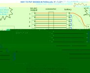
I've put diode in parallel to each DC-DC even tough if they could have some inside or not cause i want to protect them from polarity reversal.

How could it happen you'll ask?.. .ok lets suppose your complete 12s dc-dc charger is like a A123 12s battery pack.
The possibility that your pack could have cell reversal is when the very first cell would drop below 2.5 or 2.0V while you draw current on it right?.. ok now the dc dc is like every 1s cell.

If your charger that include 12s dc-dc is plugged to your battery while your controller is ON, you close the loop and current will circulate thru the cells and DC-DC.

Now, the problem of DC-DC reversal could occur when you plug your multi pins connector thst is between the dc-dc and the cells. it'S near inpossible that every dc-dc connector pair could make contact in the same time so one dc-dc will connect first and one will connect last. And i am talking about this last one that could make a problem. This could occur only when the dc-dc are not powered.


humm.. well i think i could have difficulty to explain that i french.. so could you immagine in english!! :lol:

let me give you a picture of that:

ALSO SEE SECTION 14-2 of the page 15 of the document MGDM150 from GAIA that is same similar to ARTESYN.


The current sensor are to be used to monitor each current of each dc-dc first for visual information and then for a future charge cutt off circuit. it's not necessary to use them.
 

Attachments

  • why to put diode to every DC-DC.JPG
    why to put diode to every DC-DC.JPG
    62.1 KB · Views: 2,273
  • MGDM150[1].pdf
    942.8 KB · Views: 116
Many thanks for taking the time to explain that Doc, looks like it's shottky diodes next on the shopping list then. I plan to charge at 30A for the 50Ah parallel groups so I'll need 20 x 60A doides for the 64V pack.
 
Hi everyone - intererting thread!

I like the charger idea here, but I'm wondering what this might cost to implement? I ask because I called Vicor the other day to ask how much a batmod was... and POW!...260$! each 12V 15A module. Forget them, so instead I am getting a canadian tire nautilus 3 step charger with the same output for 70 bucks. I will of course be taking it apart as soon as I get it!

While this charger is OK for my Odyssey Lead-Acids for now, it won't be for my [hopefully soon] to be perchased LIfepo4's.

What's the cheapest place for a DC-DC of OK quality for this project, any links or leads?

Thanks!
Pat
 
ZapPat said:
Hi everyone - intererting thread!

I like the charger idea here, but I'm wondering what this might cost to implement? I ask because I called Vicor the other day to ask how much a batmod was... and POW!...260$! each 12V 15A module. Forget them, so instead I am getting a canadian tire nautilus 3 step charger with the same output for 70 bucks. I will of course be taking it apart as soon as I get it!

While this charger is OK for my Odyssey Lead-Acids for now, it won't be for my [hopefully soon] to be perchased LIfepo4's.

What's the cheapest place for a DC-DC of OK quality for this project, any links or leads?

Thanks!
Pat

just go on ebay and search with: dc-dc

they usually cost around 10$ each
:wink:

for 12V output i think flip normal have some left from the large batch he bought.. ask him.

Doc
 
ZapPat said:
What's the cheapest place for a DC-DC of OK quality for this project, any links or leads?

Artesyn-BXB150-48S05 on ebay. $12.99 each. Doc's worked out how to mod them to reduce the charge current from each to 15A from 30A nominal (see earlier in this thread) if your PSU/mains supply can't take the load.

Other dc/dc converters show up on ebay in batches and can be had for less if you keep an eye out for 'em.

Doctorbass said:
for 12V output i think flip normal have some left from the large batch he bought.. ask him.
Yep, still got a few Artesyn-BXB75 12V 75W converters if anyone is interested, but they are probably best used for running lights etc. from the battery pack rather than charging lead.
 
zapPat wrote:
instead I am getting a canadian tire nautilus 3 step charger

The nautilus charger is nice! It has three amperage rates (2,10,15), a switch for regular, deep cycle, or agm batteries, the display shows both voltage and percent charge, it has auto termination, and float charge. I don't use this for bikes but it works great for 135AH deep cycle batteries. It charges faster than average lead acid chargers.
 
My Vicor mini PFC died the other night, fans come on, but no output on the 48V side. I gotta tear into it.

We put a large load on it overnight... it wasn't smoking or anything...

<---- is sad, because I was only a week away from having my BMS system assembled.
 
frodus said:
My Vicor mini PFC died the other night, fans come on, but no output on the 48V side. I gotta tear into it.

We put a large load on it overnight... it wasn't smoking or anything...

<---- is sad, because I was only a week away from having my BMS system assembled.

Oh.. that is not good...

was it fully protected with current linmit or other "over......" protections?

do you hear some strange tic...tic...tic... sound like many smps do when they are in protection mod?

Doc
 
I don't know, I didn't use it last, my coworker (designing the controller) used it.

no white smoke, fans come on still. The 3 modules inside have overcurrent and overvoltage protection. No ticking.
 
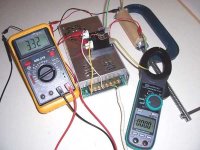
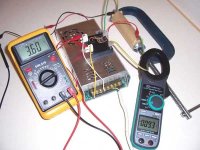
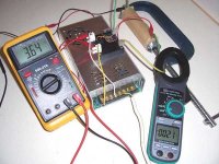
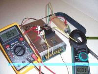
Just a few pics of my cell charging test set-up showing an Artesyn BXB150-48S05, with doc's current limit mod, charging a Headway 38120L cell. It was just a top up charge and went exactly as planned. Well it is the first time I've charged a LiFePO4 cell. 8) before charge.jpgstart charge.jpgnear end of charge.jpgend of charge.jpg
BTW the G clamp was well insulated with several layers of duct tape and the contacts were glued to thin pieces of wood so no risk of a short. Tho' I wonder what would happen if that clamp did short out the cell. :twisted:
 
Back
Top