a DC-DC to charge li-ion... GREAT!!

flip_normal said:
Just a few pics of my cell charging test set-up showing an Artesyn BXB150-48S05, with doc's current limit mod, charging a Headway 38120L cell. It was just a top up charge and went exactly as planned. Well it is the first time I've charged a LiFePO4 cell. 8) View attachment 3View attachment 2View attachment 1
BTW the G clamp was well insulated with several layers of duct tape and the contacts were glued to thin pieces of wood so no risk of a short. Tho' I wonder what would happen if that clamp did short out the cell. :twisted:


well that's a great work flip!! :wink:

be carefull with your C clamp!!

some dollar store here sale them in plastic for 1$.. .maybe you could check for some :wink:

Doc
 
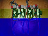
Update on the Eltek and Vicor setup...

I ended up soldering the leads coming off the bottom of the board, rather than using spades in the existing terminals. It ended up pretty straightforward once I removed two tabs off the aluminum back to make room for the wires to come out.

On the Vicors, it was very easy to use a single 2.7k ohm resistor to nail the 3.65v charge voltage. There's a nice little lead on the vicor to turn off the unit (purple and green), although I've never played with one it must be pretty easy to use some kind of dedicated voltage detection IC to hit a NC relay. I'll backup the system with a timer on the AC side.

One thing I used this weekend was an epoxy paste called PC-7. Very easy to work, not to fast not to slow on the hardening. Pretty easy to make a tough unit marine ready. These will each be attached to a battery. I've got about 40 watts a unit of heat based on the efficiency at 80 amps output, sinking, fans, keeping the leads short...
 
Lookin' very nice indeed. 8) I was wondering how I was going to cover the pins on my converters, that epoxy paste looks like it will work well. But what's this 400W out and charging at 80A :shock: How big a pack are you planning? What cells?
 
These are destined for 200 AH LiPOFe's, one for each cell. I'll be using 8 batteries in series (25.6v) and up-converting the voltage to 56v using another set of similarly sized vicors paralleled on the output end. I'll be starting on that array in a few days, and expect the batteries the end of this month.

These are for my electric boat. My goal is to keep the battery count and weight as low as possible, and increase my current range. 8 of these big batts replace 4 large 100 AH Concorde AGM's I currently have. The end result looks to be a more than 30 mile range at 100 lb, vs 20 miles at 300lb).
 
Very nice indeed powermed thanks for the post and more pics please when you get around to it.
 
ok, previous pic was one of the charge converters, here's a few of the drive converters - a 28v array capable of providing up to 1600 watts. A second array will be in series with this one.
z.
 

Attachments

  • IMG_2686.JPG
    IMG_2686.JPG
    125.3 KB · Views: 3,041
flip_normal said:
Just a few pics of my cell charging test set-up showing an Artesyn BXB150-48S05, with doc's current limit mod, charging a Headway 38120L cell. It was just a top up charge and went exactly as planned. Well it is the first time I've charged a LiFePO4 cell. 8) View attachment 3View attachment 2View attachment 1
BTW the G clamp was well insulated with several layers of duct tape and the contacts were glued to thin pieces of wood so no risk of a short. Tho' I wonder what would happen if that clamp did short out the cell. :twisted:


looking at this post, i have one convereter - mind you a tyco 3.3 volt out put -on a power supply 48 volt 10 amp and not reading any output curent infact sounds like it trips into protection mode.

my question how are you able to run just one module on this power supply ? say it provides 48 volts 10 amps the input for my module is rated at 36-75 2.4 amps so do I need to string together 4 of these modules to be able to get it to test ok?
 
efreak said:
flip_normal said:
Just a few pics of my cell charging test set-up showing an Artesyn BXB150-48S05, with doc's current limit mod, charging a Headway 38120L cell. It was just a top up charge and went exactly as planned. Well it is the first time I've charged a LiFePO4 cell. 8) View attachment 3View attachment 2View attachment 1
BTW the G clamp was well insulated with several layers of duct tape and the contacts were glued to thin pieces of wood so no risk of a short. Tho' I wonder what would happen if that clamp did short out the cell. :twisted:


looking at this post, i have one convereter - mind you a tyco 3.3 volt out put -on a power supply 48 volt 10 amp and not reading any output curent infact sounds like it trips into protection mode.

my question how are you able to run just one module on this power supply ? say it provides 48 volts 10 amps the input for my module is rated at 36-75 2.4 amps so do I need to string together 4 of these modules to be able to get it to test ok?
This is not the problem, efreak. Each low voltage converter module will use only the current it needs from the big converter, and this can go up to 2.4Amps for each one maximum. Check your datasheet for the module, maybe you are missing some kind of enable signal, or maybe it needs a minimum load attached to work correctly...
 
Thanks in advance but after closer studying of the data sheet I am even more confused.
http://www.torontosurplus.com/tes/DataSpec/Tyco_QHW100F.pdf

see in different pages they have differnt references to pin numbers and positions in one figure there are four pins with one marked case i only see 3 on my that side of module( i was worried about case grounding on my test where there were sparks ) also the orientation of the pins is diferent from page to page
i am going to use the figure on last page to be certain .
i need to short
on and off pin ( in middle supposedly) to volt--
and trim pin attached to + resistor+ potentiomete to sense+ pin

these are the two must circuitery and i also would like like docs diods for fool proofing i hope thsi works

I am putting together a charging station with 4 of these modules mounted to top frame of a 48v power supply a 8-10 amp power supply so 4 of these shouild be happy with that . this being the tester for the other charger consisting of 10 0of these modules on top of the flat pack 48v 25 amp the fit would be snug and i hope there is enough cooling supplied by the pack

pics to follow
View attachment DSC06515 (Medium).JPG
View attachment DSC06518 (Medium).JPG
View attachment DSC06519 (Medium).JPG
once i get this charger build i can start asembling the battery packs into 40 cell chunks for a 66v 9 ah total
wow taking for ever
 
Hi Efreak,

I am just curious what the spec. will be when you finish your charger ? And approx. how much it cost to make it if that is not a secret ?

Best,

Don Harmon
 
It looks like your tyco doesn't have a pin for the case, so maybe it is electricaly connected to the converter's input minus pin? You could use a multimeter on continuity or lowest ohms to check this, because it would be good for you to know since you are mounting them on the power supply housing itself.

You seem to be connecting them OK for testing, as long as you are connecting the ON/OFF pin (the one between + and - inputs) to the input minus (-) pin.

Maybe try not mounting the converter on anything for testing (no heatsink), it's OK for short tests.

Oh, I see you have the 3.3V version, I hope you can trim it up enough to get your charge voltage without triping the overvoltage protection (rated at 3.8V min, you should be good). Else think of getting the 5V instead, they usually can trim down further than they can trim up. Check page 11 to see what resistors are needed to trim up/down.

BTW, would you mind giving us an idea of the price you got from them on this converter? The web site says "call for price"... If you don't want to, no sweat either!
 
Thanks a lot for the replies.

i will check for the case continuity see if it is neutral or ground.

the cost will be the cost of the flat pack 48 volt 25 am which was very reasonable on ebay i think less than $ 200 total.
http://www.eltekvalere.com/wip4/power_racks/c/detail.epl?cat=15649
modules on ebay about $10 a peice they are retail priced at $ 139 each ( i know hard to believe) they are a lot of these available on ebay ,
according to Docbass would be good enough to charge a 4p string at a little bit above 4 amps per cell.

it is supposed to be able to trim up to 3.6 volts using proper resister and pot value(pot for adjustability) not certain what would be needed as yet.

these are ok i was told just for the lifepo4 batts they 5 volts are being used by others adjustable to do limn as well @ 4.2 volts far as i know
 
Hi efreak, did you manage to get those tyco dc/dc's working? If not then this is how I'd connect them.
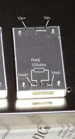
tyco dcdc.jpg
From the equation on page 11 of the datasheet, I get a value of 105 ohm for the adjust up resistor to give a 10% increase in Vout to 3.63V.

From the data sheet (page 10)

“Overcurrent Protection
To provide protection in a fault (output overload) condition,
the unit is equipped with internal current-limiting
circuitry and can endure current limiting for up to one
second. If overcurrent exists for more than one second,
the unit will shut down.
At the point of current-limit inception, the unit shifts
from voltage control to current control. If the output voltage
is pulled very low during a severe fault, the currentlimit
circuit can exhibit either foldback or tailout characteristics
(output current decrease or increase).
The module is available in two overcurrent configurations.
In one configuration, when the unit shuts down it
will latch off. The overcurrent latch is reset by either
cycling the input power or by toggling the ON/OFF pin
for one second. In the other configuration, the unit will
try to restart after shutdown. If the output overload condition
still exists when the unit restarts, it will shut down
again. This operation will continue indefinitely until the
overcurrent condition is corrected.”

Hopefully you've got the type which doesn't latch off when over current is reached.

If the Meanwell power supply limits current to 7A with 110V input ie. is a CC/CV charger, which it looks like it is, then, with four converters connected to it they shouldn't ever hit the over current point, but the Eltek will allow 25A to the converters and therefore they could trip off if the cells draw too many amps, which won't be good if they're the latch off type.

Looks like there is a similar issue with the over temp protection too, you might need to add a fan to the PSU to keep everything cool enough.

What cells are you gonna be charging with these? How many per parallel group?
 
Thanks a bunch flip i have not yet have a chance to do any more

i have 8 x a123 dewalt pack plan is to keep them attached 4 packs in parallel x 2 and charged 4 p to get 33 volt 9ah packs charging these 40 cells with charger 10 modules 11 wires in series to the 11 battery tabs ( yet to be built )

I have read that part over and over ..they have them with -Q at the end which i have a few and they must be somehow different but cant find any mention in the lit.


so that is 105 ohm thanks a lot that is a lot less than i thought like 80 k ohm with that you think probably i still need a pot for fine adjustment?

in that case an 90 ohm resistor with 30 ohm pot!?

let you know as soon as i get to test

Thanks
 
I haven't posted here in a while, but we've got our Vicor boards soldered up, and Ives at Synkromotive is working on the code.... since its microprocessor controlled and communicates over a bus (for monitoring while driving).

Its got a daisy chain bus, and a daisy chain power connection (for bussing the 48V to eachother), a fuse holder on it (auto fuses), a BRIGHT white LED to play with later (can code it to blink if there's something wrong, or identify the module through the computer over the bus). Just under 3/4 inch tall.

I can't take pictures until its done.

Some bad news..... we fried my $100 vicor power supply... at least one of the modules is bad and popped a fuse between the HV bus and the 3 DC-DC converters onboard. So either I've got to get it running with 2, or find another supply.

I'll update next week, because it'l be scalable with Lifepo.
 
frodus said:
I haven't posted here in a while, but we've got our Vicor boards soldered up, and Ives at Synkromotive is working on the code.... since its microprocessor controlled and communicates over a bus (for monitoring while driving).

Its got a daisy chain bus, and a daisy chain power connection (for bussing the 48V to eachother), a fuse holder on it (auto fuses), a BRIGHT white LED to play with later (can code it to blink if there's something wrong, or identify the module through the computer over the bus). Just under 3/4 inch tall.

I can't take pictures until its done.

Some bad news..... we fried my $100 vicor power supply... at least one of the modules is bad and popped a fuse between the HV bus and the 3 DC-DC converters onboard. So either I've got to get it running with 2, or find another supply.

I'll update next week, because it'l be scalable with Lifepo.
I don't know if this may have anything to do with it or not, but make sure that you use bolts through the Vicor power supply's mounting holes, even when it is not mounted to anything. This is to make sure the sandwich between the heatsinks stays compressed enough to transfer heat well from the center. I use a 6" PC fan to cool my vicor PS, mounted flush against the larger heatsink side. Do you know the cause of loosing one module out of three on the Vicor PS? I assumed they were very well protected...

I am looking forward to seeing your charging setup completed, it sounds interesting. It would be great to have a BMS that can communicate with the controller, is this what you mean by bus communications?
 
we know what was wrong, we used it for testing something else, and it had a ton of noise on it.... the current spikes kinda screwed it up.

And yes, thats what we mean by the buss comm.... all daisy chained.
 
I made an offer at http://www.hkyixin.net for 80 BXB150-48S05FLT units at $10 per unit, and the offer was accepted. Maybe I should have gone lower. Anyone here still interested? Perhaps we could group buy more units for a lower price. I'm located in the USA, and I'd be happy to forward units to Canada.

Perhaps an introduction in also in order. I recently finished converting a Geo Metro convertible to an EV. It has 2 strings of ThunderSky cells in parallel. Each string has 35 cells. One string is 90Ah cells, and the other is 200Ah cells, giving a total of 36Kwh. Range is 144 miles to 100% DOD, 114 miles to 80% DOD, and 88 miles to 60% DOD, which is great, because 88 miles is my daily round trip commute.

I'm thinking of putting one DC/DC module on each cells, a total of 70 modules, and using them in two ways:

1) Charging: Hook DC modules to 48V lead-acid pack. Lead acid pack is charged by 50A or 100A (2 50's in parallel). No current limiting necessary, because the cells can handle 39A

2) Balancing and Assist during driving: The end of my commute is a 1700-ft. climb over 6 miles. I want to flip the DCs to 3.3V and leave them connected to the fully-charged 48V PbA cells. That way, whenever the cells sag below 3.3V, the PbA pack will kick in and provide the extra juice needed. Also, this will help with pack balancing, since whenever the cells fall below 3.3V, they get topped off to 3.3V.

To see my the video of my first drive of the car, go to YouTube and search for this exact phrase:

"Electric Car First Rides"

Bill Dennis
 
Question: When I connect one my dc modules to the 48 volt power supply the power supply makes a rather high pitch noise. and no reading on the out puts.

does that mean the module is no good? or what else couild it be?
 
Hi Bill,

I bought my BXB150-48S05FLT's from this ebay seller and was quoted $11.50 each on 100. I bought two dozen from them and was happy with the service, they were very well packaged and all work fine. You may well save a few bucks on shipping and brokerage fees even though the unit price is a bit more. Just a thought.

Nice car, how much lead are you carrying, AHs, weight?

What motor/controller do you use and what's your top speed? How many amps does it pull at top speed/cruising?

Luke.
 
efreak said:
Question: When I connect one my dc modules to the 48 volt power supply the power supply makes a rather high pitch noise. and no reading on the out puts.

does that mean the module is no good? or what else couild it be?

If the power supply usually works OK then it looks like the converter is a dud. Sad to say :(
 
Thanks again Flip

Now I am wondering is it something that I am doing that needs to be looked at .

do I need to add anything on the load end before testing the module? or is it over heating burning before i get a reading?

in other word is there a safe way to determine health of modules before hand?

I know the supply is working

thanks
 
Luke,
No lead yet, just the 290Ah of ThunderSky lithium cells mentioned in my first post. Top speed is 90mph. Cruising at 60 mph draws 100A. Averaging around 225 Wh/mile. Cells currently getting too hot on extended commutes though (50 degrees C), so I'm going to have to install some type of better cooling than just airflow.

Just a Curtis 1231C controller. 8-inch ADC motor.

Thanks for the tip on the Ebay seller. I actually bought 1 unit from him about 4 days ago (hasn't arrived yet), but I didn't know that he had more in stock. I've sent him a message asking if he can supply 80.

Bill Dennis
 
Back
Top