A No Solder/Weld 18650 Build

Be careful with the foam compression. Some foams lose their compression 'push' and become flat from the constant pressure.

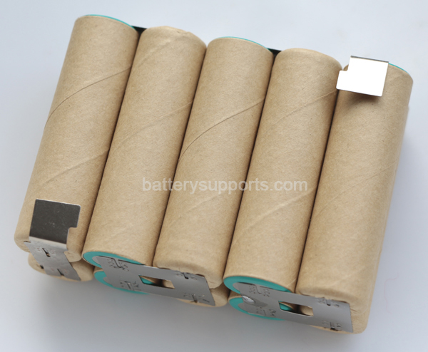
I did my first battery build like this, but with springs. I think I lost a lot of power to resistance. Mine was a complete hack job, not anything as nice as yours.
 
veloman said:
Be careful with the foam compression. Some foams lose their compression 'push' and become flat from the constant pressure.


It's called 'set'. Many types of foams are effected by it, but some have very minimal set properties.

Google "low compression set foam" if you want to know some available options.
 
That is really cool, very well done. I just love how everything about this battery is easily replaceable if need be. I've been looking at building a spot welder and started gathering parts for it. Now that I see this, I'm thinking why bother :D Any ideas if a heating system could be integrated in this? Up here in Canada, we have to heat up our batteries.
 
mistercrash said:
That is really cool, very well done. I just love how everything about this battery is easily replaceable if need be. I've been looking at building a spot welder and started gathering parts for it. Now that I see this, I'm thinking why bother :D Any ideas if a heating system could be integrated in this? Up here in Canada, we have to heat up our batteries.

You might try here. I believe some of the thin film/printed heaters would work.

http://www.tempco.com/Surface%20Heaters/FlexibleHeaters_hub.htm
 
snath said:
Someone above asked about connections resistance. I took a AA (no extra 18650s :oops:), chucked it up in the lathe and pressed a dimple and piece of foam against the end of the cell with the end of a boring bar until it made contact and then advanced it 1/32" (to emulate the compression in the pack). I checked resistance of the contact/connection and it read 0 ohms with my two decimal place ohm meter.
That is not how you measure contact resistance the correct way.
You should load the battery by 1amp precisely and then measure the loss in millivolts across the battery to copper connection using a good multimeter (e'g Fluke) with 3 digit tolerance in the millivolt settings.
One prope at the battery pole, the other at the copper bar. Each millivolt measured equals 1 milliohm in contact resistance. This is the only correct way to properly measure contact resistance.
 
You don't need to apply a precise voltage or current, as long as you can measure them reasonably accurately. Then just divide your measured voltage by the measured current to get the resistance.
 
Correct!

But the ones that have precise current adjustment can enjoy quick and easy amp reading.
At work I always use a 0.01R shunt at 0.1% tolerance, where each 10mV gives me 1Amp reading....lazy mans setup :)
 
Snath I think you have done a great job here, it had crossed my mind to use the 18650 cells for a pack build but was put off not only by the logistics of cell connections but also the costs. What price are you getting the cells for, here in the uk they are vastly more expensive when compared to an equivalent AH pack made from HK lipo?
 
dnmun said:
what are the spacing rods made of? you drilled and tapped each end of the rod for a cap screw to secure the compression plate?
The spacer rods are made of 1/4" PVC rod. I got it (and the PVC sheet) from McMaster Carr.
That is correct, I cut them to length and drilled and tapped each end. The sides and spacer rods are the same height/length.
 
Tench said:
Snath I think you have done a great job here, it had crossed my mind to use the 18650 cells for a pack build but was put off not only by the logistics of cell connections but also the costs. What price are you getting the cells for, here in the uk they are vastly more expensive when compared to an equivalent AH pack made from HK lipo?

I don't recall exactly how much I paid for them, maybe $7.55 each with free shipping. Here in the US, I like Orbtronic.

You are correct, they are way more expensive but from a weight, volume, quality, and build-ability standpoint, the 18650s win hands down.

I have some of those 18650 spacer blocks on order and when I get them, I'll do another build with bus bars that is vastly more simple... no spacers to cut because the battery/spacer blocks will set the height and, a whole lot fewer screws. Still will be using the compression blanket concept though. The case will be solvent welded acrylic. That will ease fabrication because you can just score and break it...... no sawing.
 
Hi,

spinningmagnets said:
If such a case as this had the ability to accept strip-welded parallel groups that just dropped in (as opposed to loose individual cells being the only option) then I think the bus connections would be less of a concern, since several springs touching the 5-cell group would mean there is always at least one or two with a secure connection? I'm not saying that a clamshell case like this should only accept single cells, or groups of strip-welded cells...I just think that it should be reasonably easy to make a minor adjustment so that a case could be made and/or sold, and the builder/buyer has the choice. Here is a pic of what I mean:

file.php
Building a case with a compression blanket etc. to accept strip-welded parallel groups of cells seems like a lot of unnecessary work to me. You could just drill small holes in the welded strip and use bolts to fasten crimp on eye connectors or spade connectors to the strips:
979913-1.jpg

spadeterminals.jpg
 
Nice! I have been wanting to use 18650 without soldering for awhile now. I have an idea using air pressure but have yet to start. I figure if you have two air bags connected as one pressurizing each side of the cells then some kind of spring system you can make a makeshift kind of shock protector allowing the pack to move slightly with vibrations/bumps along with the air pressure/springs holding them in place. Like others have said in this thread still not sure about the resistance.
 
silviasol said:
Nice! I have been wanting to use 18650 without soldering for awhile now. I have an idea using air pressure but have yet to start. I figure if you have two air bags connected as one pressurizing each side of the cells then some kind of spring system you can make a makeshift kind of shock protector allowing the pack to move slightly with vibrations/bumps along with the air pressure/springs holding them in place. Like others have said in this thread still not sure about the resistance.

In my opinion, air bags would be a lot of hassle to make..... the urethane blanket is pretty simple, all you have to do is cut it to size and punch the holes for the spacer bars.
As far as resistance goes, I defer to LFP's assessment (above) that the pack resistance would be low.
 
IMO anything that is not pressurized is going to compress overtime though, I would think quickly seeing as how 30+ on a bike is going to make alot of vibrations. Another thing I was thinking is just a small air tank to a regulator then to some large syringes with springs in them. Maybe implant them into the frame. I am too satisfied with my lipo with pcm/bms right now to continue with the project though.

I actually do alot of stuff with copper sheet myself. Is that is that 24 or 30 ounce sheet? What kind of machine are you using to punch the holes? If one were to punch a larger hole, say .75", would it come out perfectly flat and unwarped? I would have a new toy to buy for my workshop :twisted:
 
silviasol said:
IMO anything that is not pressurized is going to compress overtime though, I would think quickly seeing as how 30+ on a bike is going to make alot of vibrations. Another thing I was thinking is just a small air tank to a regulator then to some large syringes with springs in them. Maybe implant them into the frame. I am too satisfied with my lipo with pcm/bms right now to continue with the project though.

I actually do alot of stuff with copper sheet myself. Is that is that 24 or 30 ounce sheet? What kind of machine are you using to punch the holes? If one were to punch a larger hole, say .75", would it come out perfectly flat and unwarped? I would have a new toy to buy for my workshop :twisted:

Others have commented on using some type of air compression system but, personally, I think it's overkill and wayyyy too complicated.

I don't know what my copper sheet is in ounces, but I can tell you that it's 10 mil thick. I use Roper-Whitney punches in my fly press to punch holes. If you wish to know more about fly presses and tooling, you might be interested in this web page. Punch tooling is about two thirds down the page. My press is a size 0, a baby one.
 
snath said:
silviasol said:
IMO anything that is not pressurized is going to compress overtime though, I would think quickly seeing as how 30+ on a bike is going to make alot of vibrations. Another thing I was thinking is just a small air tank to a regulator then to some large syringes with springs in them. Maybe implant them into the frame. I am too satisfied with my lipo with pcm/bms right now to continue with the project though.

I actually do alot of stuff with copper sheet myself. Is that is that 24 or 30 ounce sheet? What kind of machine are you using to punch the holes? If one were to punch a larger hole, say .75", would it come out perfectly flat and unwarped? I would have a new toy to buy for my workshop :twisted:

Others have commented on using some type of air compression system but, personally, I think it's overkill and wayyyy too complicated.

I don't know what my copper sheet is in ounces, but I can tell you that it's 10 mil thick. I use Roper-Whitney punches in my fly press to punch holes. If you wish to know more about fly presses and tooling, you might be interested in this web page. Punch tooling is about two thirds down the page. My press is a size 0, a baby one.

Forgot to add the link :oops: http://www.abana.org/ronreil/flypress.shtml
 
You could just drill small holes in the welded strip and use bolts to fasten crimp on eye connectors

Thats an excellent suggestion, these suppliers of paralleled sub-packs already provide longer strips if requested at no extra charge! They will orient the excess tab length in any direction you want.

Makita%20BL1830%204Ah%20Repair%20Battery%20Pack_04.jpg
 
silviasol said:
IMO anything that is not pressurized is going to compress overtime though, I would think quickly seeing as how 30+ on a bike is going to make alot of vibrations. Another thing I was thinking is just a small air tank to a regulator then to some large syringes with springs in them. Maybe implant them into the frame.


Silviasol- Not all materials have set issues. There are many options that will never set and release pressure over time. Discussing pneumatic bladders for pressure is simply adding a bunch of complexity to attempt to fix something that is only a perceived problem yourself and others see, not an actual issue.

Imagine the right foam being a cluster of hundreds of thousands of tiny sealed air-bladders. :)
 
snath said:
snath said:
silviasol said:
IMO anything that is not pressurized is going to compress overtime though, I would think quickly seeing as how 30+ on a bike is going to make alot of vibrations. Another thing I was thinking is just a small air tank to a regulator then to some large syringes with springs in them. Maybe implant them into the frame. I am too satisfied with my lipo with pcm/bms right now to continue with the project though.

I actually do alot of stuff with copper sheet myself. Is that is that 24 or 30 ounce sheet? What kind of machine are you using to punch the holes? If one were to punch a larger hole, say .75", would it come out perfectly flat and unwarped? I would have a new toy to buy for my workshop :twisted:

Others have commented on using some type of air compression system but, personally, I think it's overkill and wayyyy too complicated.

I don't know what my copper sheet is in ounces, but I can tell you that it's 10 mil thick. I use Roper-Whitney punches in my fly press to punch holes. If you wish to know more about fly presses and tooling, you might be interested in this web page. Punch tooling is about two thirds down the page. My press is a size 0, a baby one.

Forgot to add the link :oops: http://www.abana.org/ronreil/flypress.shtml

10 mil sheet is .01" or about a quarter of a mm thick, I am sure it isn't that. There are only so many thicknesses 16oz, 20oz, 24oz... I think they raise 4 oz each size up, I have had a max of 48oz. That is how many ounces it weighs per square foot. I would think you have 24 or 32oz which is common to find at sheet metal shops, 32oz is almost the thickness of a penny and 24 about half.

I see they are a slow working machine that you spin to compress which will not work at all for what I do. I use a foot shear to cut small cuts of copper hundreds at a time, it would be nice to have circle pieces but don't charge much for them so time is an issue.

liveforphysics said:
Silviasol- Not all materials have set issues. There are many options that will never set and release pressure over time. Discussing pneumatic bladders for pressure is simply adding a bunch of complexity to attempt to fix something that is only a perceived problem yourself and others see, not an actual issue.

Imagine the right foam being a cluster of hundreds of thousands of tiny sealed air-bladders. :)

Yes I guess I did not imagine anything would not wear or permanently compress over time. However what are the specs of the material, I assume there is a max amount of pressure that can be applied before permanent compression may occur? Sharp bumps are going to multiply the pressure already applied by alot, for a quick second each time however that would add up over time. Say it can handle 150psi, how much extra psi will a bump create when it is already at 150psi. That is my thought however the cells being horizontal with the frame would probably eliminate shock so long as the cells will not displace or vibrate vertically.
 
45g on an 18mm radius taking a 10G impact (this would make a 60lbs ebike weigh 600lbs, and a 170lbs body 1700lbs), is still only 2.53psi. Even if you were 4 18650 layers deep you would still be way inside the always elastic region of many low-set foams.

Its crazy how much of this awesome pack thread has been foam set fixated. lol

Here are some examples of types of foam that are able to supply more than adquate pressure for at least decades.

http://www.silicone-sponge-supply.com/Silicone_Sponge_Silicone_Foam/Low_Compression_Set_Silicone/low_compression_set_silicone.html

This page gives a pretty good overview of various materials set properties.

http://www.dkirubber.com/materials.asp
 
spinningmagnets said:
Since building a pack with your pattern of strips would require that the builder have a DIY spot-welder, then repairs to replace a bad cell could be made fairly easy. I have had good luck cutting these strips with a Dremel and a thin abrasive wheel (to disassemble cordless drill packs), and I think it may be useful to consider also making a "repair kit" that might look something like this:


I believe you misunderstand how this pack is built. As the post title, and the pictures, sort of, clearly indicate there, are no strip to battery welds..... You can remove the cover, lift the bus bars, and lift each cell out one by one.
 
Ok, here's the deal, my goal in building this pack was to show a way that a pack can be built without a lot of technology while, at the same time, providing a stable platform for attaching to a bike. I missed the mark a little. So No Solder/Weld 18650 Build Version Next, as I mentioned previously will be a little different and much more simple.

I've gotten a bunch of those cell mounting blocks, Have another 50 cells on the way, and am putting the finishing touches on a new "smack it (lightly) with a hammer" dimpling jig (This the only part that will require machining. But, that can be farmed out if necessary.). Next, we'll get some acrylic, and some methylene chloride or IPS16 (for simplicity, I plan to scribe and break the acrylic so a little thicker solvent may be necessary) to weld up a battery case, and some more foam (YES DAMMIT, FOAM. As food for thought, look at all the foam gaskets on an automobile) to make our bus bar to cell connections and provide some shock absorbance.

Over the next few posts, I'll try to build a battery that NaturalPath, who bemoaned the tool intensiveness, of this last build can put together. Oh yes, there will be a whole lot fewer screws. :D
 
Back
Top