A PIC based Battery Management System

http://www.microchip.com/stellent/idcplg?IdcService=SS_GET_PAGE&nodeId=1335&dDocName=en026564

This powerful yet easy-to-program (only 35 single word instructions) CMOS FLASH-based 8-bit microcontroller packs Microchip's powerful PIC® architecture into a 44 pin package.The PIC16F884 features 256 bytes of EEPROM data memory, self programming, an ICD, 2 Comparators, 14 channels of 10-bit Analog-to-Digital (A/D) converter, 1 capture/compare/PWM and 1 Enhanced capture/compare/PWM functions, a synchronous serial port that can be configured as either 3-wire Serial Peripheral Interface (SPIâ„¢) or the 2-wire Inter-Integrated Circuit (I²Câ„¢) bus and an Enhanced Universal Asynchronous Receiver Transmitter (EUSART). All of these features make it ideal for more advanced level A/D applications in automotive, industrial, appliances or consumer applications.

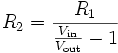
That's great. You could do nothing but voltage dividers that feed directly into the PIC16F884's 14 A/D pins and then run the software to correct for error. A real no-brainer.

This looks very good... :D

You can go up to 44.8 volts with this. (14 * 3.2v)


file.php


:arrow: Let me propose one idea...

Since these PIC chips are burned in before being installed you could gather together the resistors you were planning to use for voltage dividing and using your best multimeter measure the precise resistance that they make. You then enter those values into the software as hardcoded initial values for your abstract model. You can then burn in the chip. Once installed the results should be pretty good as long as the deviation of the resistors is small. (things like temperature will cause error, but if that's small enough relatively speaking you could live with it)
 
The 10 kOhm limit is from their datasheet. As far as I understand it has to do with charging a capacitor and leakage currents distorting the measurement. On this doc:

http://ww1.microchip.com/downloads/en/DeviceDoc/41291E.pdf

On page 107 (section 9.3) they describe ADC equivalent circuit and lots of info about how to use it. The higher the impedance the slower the speed becomes and it doesn't work above 10k it seems.

There's more on page 90 (section 8.7)

The good news is ADC can go from ground to supply voltage and then a bit. So cpu/adc can be driven directly from the cells.
 
tomv said:
The good news is ADC can go from ground to supply voltage and then a bit. So cpu/adc can be driven directly from the cells.
:!: Wow! Is that for real? Are you saying that you could potentially use a common mode voltage of 44.8 volts in the ADC? There has to be some limitation about amps because you can't just let the thing absorb the full force of the cell.

:arrow: I want proof of this!
 
safe, VCC is the supply voltage of the MCU, which would be about 5V not the pack voltage. about the optos i was talking about before, thats not for measuring the pack voltage, that was for balancing the cells, the MCU would turn on the opto and bypass current around the cell to slow its charging so the others catch up.

with the mux and differential amp you don't need to worry about the value of the resistors, the input to the ADC is from the op-amp which has low impedance.

using an op-amp on each cell doesn't really solve anything, if the pack is 72V then you need op-amps that can operate at that many volts, and each op-amp needs to have 4 resistors, then they still all need to go to a mux, if you just use a mux and one amp, you just need 2 resistors for each cell, and you can eliminate the problem of the pack slowly discharging through the voltage dividers by grounding all the resistors through a single fet that can be turned off/on by the MCU. the voltage drop across the fet is the same for all dividers so everything is just dandy.
 
dirty_d said:
...the MCU would turn on the opto and bypass current around the cell to slow its charging so the others catch up.
So it would basically form an alternative path that would "waste" some current that would normally go into the cell. The idea is to "dump current" right? A picture would be nice still.

dirty_d said:
...with the mux and differential amp you don't need to worry about the value of the resistors, the input to the ADC is from the op-amp which has low impedance.
But that was the whole point about the PIC16F884 chip it has enough pins (14 Analog to Digital converters) to handle a pack up to 44.8 volts. Assuming you use just one cell per 3.2 volts. In other words get big cells and not a lot of small cells. These days you can choose up to 90 Ah in a cell so there's no reason to be using the small one's anymore. (there's no reason to do parallel anymore)

:?: Why use a multiplexer if a PIC can handle all the inputs directly? (the software correction is not a big deal to do)
 
safe said:
So it would basically form an alternative path that would "waste" some current that would normally go into the cell. The idea is to "dump current" right? A picture would be nice still.

you have already seen it in my lipo charger thread.

44 volts isn't very much, you want something that scales well, with one 8 bit port on the MCU you can switch 256 cells with 17 16-channel muxes. thats a whole lot of stuff, but you see it scales very well.
 

Attachments

  • balance.jpg
    24.3 KB · Views: 2,235
19-Channel Analog to Digital Chip?

I'd be happy with a 36 volt system for my own purposes because for something like Thundersky cells buying more than 12 gets expensive. (and more complicated) But you could also just get something like this.

:arrow: 19 channels would translate to 60.8 volts.

(you would need 72v / 3.2 = 22 channels for 72v)
 

Attachments

  • 19 Channel Analog to Digital.gif
    19 Channel Analog to Digital.gif
    15.7 KB · Views: 3,901
you need at least 10 bits, with 8 bits on a 0-5V range you only have 19mV resolution. i don't see the advantage over a mux anyway, thats going to be more expensive and it looks much more difficult to control.
 
safe said:
:!: Wow! Is that for real? Are you saying that you could potentially use a common mode voltage of 44.8 volts in the ADC? There has to be some limitation about amps because you can't just let the thing absorb the full force of the cell.

:arrow: I want proof of this!

I'm not saying ADC can measure 44.8V, i'm just saying that it can measure up to supply voltage that can be 2V to 6V. The datasheet says this:

"The analog input, therefore, must be between VSS and VDD. If the input voltage deviates from this range by more than 0.6V in either direction, one of the diodes is forward biased and a latch-up may occur."

What I'm thinking is if it is possible to use cell output to power PIC directly. So first cell in my pack (or a few cells in parallel) is the cpu supply at 3.3V, and as long as you divide all other cells down to less than 3.3V then you don't need any other voltage regulation.

PIC uses 0.4 mW at 4Mhz (full speed) and 0.02 mW in low power mode (33kHz) so it won't unbalance cells much.
 
Many solutions are possible obviously, so at some point we might have to decide how flexible this might be. If all you have in mind is a 36 volt pack and simple series cells (no parallel to confuse matters) then the PIC16F884 with it's 14 Analog to Digital input pins could handle the voltage divided cell wires without multiplexing. From then on it's all software and deciding how to use the knowledge the system is designed to collect. If the goal is to "get the job done" and your parameters are within this spec you could do it pretty easily. However, if you want to do more and make this something more universal then you would have to make it more complicated. I think the whole idea was to reduce components as much as possible and drive the price down.
 
dirty_d said:
you have already seen it in my lipo charger thread.

Could you include a link to that thread? It would probably answer my questions about your balancer. Right now I'm thinking "This is really nice, but maybe something simplier would work". I'm thinking about balancing as done in Atmel reference design (AVR453) .

- You can cut charging when the weakest cell in your pack is fully charged. Even if stronger cells can take more charge, when discharging you'll have to cut off the pack the moment weakest cell is empty. So why do you need shunt bypass around the cells?

- It's ok if balancing takes days, it can continue after pack is unplugged, discharging and it doesn't have to be over in one charge-discharge. As long as balancing is faster than unbalancing (hundreds of cycles normally) it's ok. Atmel recomends 2mA balancing current.

- Atmel design does balancing by placing FET and resistor across voltage measurment pins so no need for voltage isolation. But it won't work with voltage dividers, so I'm thinking how to solve that.
 
so basically the question is, what is cheaper? 14 op-amps with 4 resistors each and one MCU with 14 ADC channels, or 28 resistors, one op-amp, one mux, and the MCU(which needs only 1 ADC channel).

you cant really get away without using the op-amps and just dividing the voltage straight to the ADC. the ADC only has a certain amount of resolution, lets say you have a 10-bit ADC with a absolute accuracy of +-2LSB and a 44.8V battery, +-2LSB means that the calculated number can be off by the value of the least significant bit times two. with the ADC range of 0-5V the least significant bit represents 4.9mV so the value you get is only going to be within 9.8mV of the actual voltage, the value you get in your program code is a 10-bit value 0-1023, so 0 represents 0V, 1 represents 4.9mV, 2 represents 9.8mV ..... 1023 represents 5.0V. now if you have a 10:1 divider on the cells the 14th cell(44.8V) will be 4.48V to the ADC, now with the max error or the adc lets say in our program we get 4.48 + 0.0098 = 4.49V(919 in the MCU). now that doesn't look too bad right? wrong, we have to multiply it by 10 to get the real voltage of that cell from ground then subtract the voltage of the previous one to get the actual voltage of cell, so 4.49 * 10 = 44.9V, oops! thats 0.1V off fro the cells actual voltage to ground of 44.8V! that just wont do. when you divide the voltage then convert it to binary you lose information, and you cant get it back, thats why its best to use a differential amp to find the difference between two cells adn input that to the adc, that way the calculated voltage is within .0098V from the real voltage instead of 0.1V.

i probably did a shitty job of explaining that :oops:

tomv, here you go http://endless-sphere.com/forums/viewtopic.php?f=14&t=3329
 
As I see no way to do cell balancing without optocouples, then maybe using optocouples can help in measuring voltage too.

Sofar it would be 2 resistors + 1 2 channel opto per cell. Total pack is 2N resitors, N optos and MCU for up to 12 cells. In my opinion it scales ok, as packs can be chained in series. Could even use optocouples to make MCUs talk to each other via serial bus if necessary.

Safe pointed out that optocouples wear out, but I see that there are some with guaranteed life of many years. I'll dig up datasheets.
 
dirty_d said:
so basically the question is, what is cheaper? 14 op-amps with 4 resistors each and one MCU with 14 ADC channels, or 28 resistors, one op-amp, one mux, and the MCU(which needs only 1 ADC channel).
You are forgetting option three which is the cheapest:

:arrow: 2 * CellCount = 24 (for a 36 volt system) Resistors.

:arrow: 1 PIC with 14 Analog to Digital converters built in to it.

...the resistors are of progressively more and more imbalance from low to high cell so that the output remains roughly equal to the cell voltage. (so when you read 3.2 volts that means that the cell is equal to 3.2 volts) As long as all the cells are balanced this remains true, but if they become imbalanced you can use software to correct the error in the results. That's the whole point of what I've been saying. (and it seems like you are not really getting my idea)

:idea: At least let me know that you comprehend fully what I've presented. A lot of the time we all tend to bounce off each others postings without getting the subtle twist that the person is trying to present. I do the same thing and am now trying to make a habit of actually trying to figure what is being said. (as best I can)
 
tomv said:
Safe pointed out that optocouples wear out, but I see that there are some with guaranteed life of many years. I'll dig up datasheets.
They keep working for years, but if you are expecting to get an analog result your results will drift with time. As the LED ages it gets weaker and that means the signal is less with time. If you have some way to correct the error as it ages you would be okay or if it was a binary on or off situation you would be fine... just don't expect the output to be constant.

Bob Mcree's LVC is a all or nothing proposition. When the Voltage Detector triggers the optocoupler passes the result along by triggering a full voltage response.
 
safe, read the part of my last post about the ADC error carefully, you cant correct for that(you can reduce the actual ADC error but you cant help that the error is multiplied by 10 if you use 10:1 dividers).
 
dirty_d said:
safe, read the part of my last post about the ADC error carefully, you cant correct for that.
Yeah, you are still not getting my idea.

Let me try again...

The first cell has a voltage of 3.2 volts so the voltage does not need to be divided and you can pass the full 3.2 volts to it's pin. The second cell starts at 3.2 volts and goes to 6.4 volts. So in that case you need to divide in half so that it goes from 1.6 volts to 3.2 volts. The third starts at 6.4 volts and goes to 9.6 volts so you need to divide by one third, so you still get from 2.4 volts to 3.2 volts.... and so for 35.2 volts to 38.4 volts you need to divide by twelve so you get from 2.93 volts to 3.2 volts. You now take these values from 0 volts to the cell voltage for all the cells and run them through an algorithm that compensates when the results are not balanced. Once you correct for error through software you can actually know what you have. The level of precision of your resistor measurements is critical to getting the right result. (you would probably want to get an extra level of precision on the resistor measurement)

:arrow: Is this how you envisioned it?

I'm doing the math differently than you are doing it because I'm not dropping everything down equally. The precision is moved to getting the resistor values right and using an algorithm to calculate the circuits distortion behavior. I'm pretty sure that this increases your significant values in the calculation.

However, you do raise a good question about the limits of precision on this type of system... :shock:

It's becomes clear that the error increases as the voltage of the cell increases. So the first has great precision and the last one has "CellCount" times worse precision. But since the error propagates from the low to the high cell voltage and increases with each added cell the process of getting the maximum precision for each cell along the way does lower the overall error. If you divided by 10 for everything your error increases rapidly from the start rather than only showing up at the end.


Resistor Values = 1 + Cell_2 / 2 + Cell_3 / 3 + Cell_4 / 4 ... Cell_N / N
 
dirty_d: thanks for the thread, it's a gold mine!

isolators i was thinking about are Analog iCoupler, but they are digital only. The good things about them is they don't wear out and use very little power. I wonder if that can be useful somehow.
http://www.analog.com/en/subCat/0,2879,767%255F827%255F0%255F%255F0%255F,00.html
 
safe, yea thats what i thought you were doing, thats exactly the same way i originally planned on making my lipo charger but i saw the flaw in it. to correct for the error in the cell voltages you start from cell1 which already is perfect, and for cell2 you multiply by two and subtract cell1 from it to get cell2's real voltage regardless of how out of balance cell1 is, heres an example:

cell1: 3.3V, 3.3V from ground, 3.3V to ADC
cell2: 3.1V, 6.4V from ground, 3.2V to ADC

cell1 is fine as is we get 3.3V

to calculate the voltage of cell2 you do this:

3.2 * 2 = 6.4
6.4 - 3.3 = 3.1V

see that works but any error in the calculated value got multiplied by 2, for the 14th cell it gets multiplied by 14. i cant think of any way around this, think about it some more and let me know if you find another way.
 
I have the solution for real this time

We need to use 4 channel optocouplers and a multiplexer to measure the high voltage cells. THere's no way to directly measure a 60v voltage without using voltage dividers. We need the optocouplers to switch each cell so the voltage dividers can measure. Like this:
The big six-way switch in the middle representss a quad optocoupluer. For a battery pack with 16 batteries there would be 4 quad opto. THe PIC would use a 16 channnel multiplexer to turn on one optocoupler at a time and then take the ADc.


optocoupler
http://search.digikey.com/scripts/DkSearch/dksus.dll?Detail?name=160-1364-5-ND

THe ADC would have 10 bit resolution so it ranges from 0 to 1024. this will cover a range of 4 batteries or 14.2v. So the resolution would be about 0.02v which is good.

Problem solved
 
Beagle123 said:
Problem solved
Yeah, well the problem with optocouplers is that they need to have an "off switch" when not in use otherwise they wear out and their output voltage degrades. The problem is that the multiplexer needs to be the "off switch" for the optocouplers and that would place it on the power side of the optocoupler. And if you did do that the mulitplexer would need to be able to handle the high common mode voltage. You need a solution like Bob Mcree uses for the LVC where the "off switch" is in front and not behind.

I downloaded the pdf for that optocoupler and it's just a regular one. What would be needed is a combination optocoupler and multiplexer... that would be really cool... because then you could turn it off when not in use.
 
dirty_d said:
to calculate the voltage of cell2 you do this:

3.2 * 2 = 6.4
6.4 - 3.3 = 3.1V
:shock: I see your error.

The full "abstract model" that needs to be created will make use of every resistor in the system. It's very likely going to be an equation that will have a total of "N" times "2" resistor data constants in it. You can't do that sort of simple math with direct multiplication and expect a true result.

I took a Numerical Analysis class in college and there are tricks with computers to ensure you get better precision in your calculations. Basically you would want to take you 8 or 10 bit data and expand it to 20 bits or more during the calculation. Then when you arrive at the result you trim it back down. The result is a lot higher precision.

At some point the actual "abstract model" needs to be discussed. We've sort of been skipping past that... that's the central philosophical problem to resolve.

Also, another reason the direct multiplication route doesn't work is that when cells are not balanced the output gets totally deformed by it. I proved that on an earlier posting... only in the special case of perfect balance does the simple direct multiplication algorithm work.

:arrow: This is a solvable problem, but we are going to have to go a lot deeper in thought to arrive at the "abstract model".

http://en.wikipedia.org/wiki/Solvable_group
 
The Abstract Model

http://en.wikipedia.org/wiki/Voltage_divider

As a simple example, if R1 = R2 then

d700c5bf60999c3deb7bd4c68998b846.png


As a more specific and/or practical example, if Vout=6V and Vin=9V (both commonly used voltages), then:

06f0d77c0455b0c216d4a07215ba3081.png


and by solving using algebra, R2 must be twice the value of R1.

To solve for R1:

3db7631c0aa17b19db461b8e30aa41de.png


To solve for R2:

1dfb9c4ea70235c81dd0ce52c99160c3.png


Any ratio between 0 and 1 is possible. That is, using resistors alone it is not possible to either reverse the voltage or increase Vout above Vin.


So the basic idea is to work backwards from the output and knowing the values of the resistors as constants you can calculate backwards to find the original voltage. So know what "Vout" is, but we don't know what "Vin" is for our voltage divider circuit. And we also have to account for the overall relationships between cells since cell imbalance means that you cannot solve each cell in isolation. So the actual equation will be long... the algorithm will require a loop through all the voltage dividers.

:arrow: A Comment:

Anyone who has created electronic circuit simulation software would know this stuff like the back of their hand... all the simulations do this sort of thing. So the secret would be to find someone with that narrow expertise. The knowledge is out there, so we could "reinvent the wheel" or we might be able to discover it someplace.
 
why even get the resistors involed in the calculations, you know that the first voltage divider divides the voltage by two, and if not, you measure how much it actually gets divided by and create an error correction value, but this is all pointless as the end result is increasingly shitty as the voltage goes up, in my opinion the best way to do this whole deal is to use equal dividers on each cell going to a dual chanel mux then to a calibrated differential amp, then to the MCU's ADC. resistors are dirt cheap and you only need one op-amp, the MCU will probably be $2-4 and you only need one, the only thing that might be a lot is the mux, i saw two for $9 that have 32 channels and another that has 16 channels but dual output. thats really not bad and it is still simple.

safe said:
Also, another reason the direct multiplication route doesn't work is that when cells are not balanced the output gets totally deformed by it. I proved that on an earlier posting... only in the special case of perfect balance does the simple direct multiplication algorithm work.

yes, it does. i showed you the work, now try it yourself, make a list of made up cells with out of balance voltages then solve them with the divided voltage and that math. it works. you keep track of the so far calculated pack voltage to correct for the cells being out of balance.

if you want me to prove it make up a 5 cell pack with unbalanced cells with perfect dividers on the taps cell2's divider dividing the voltage by 2 and cell5 dividing it by 5, then give me the divided voltages at the taps and ill give you a list of the actual cell voltages regardless of how out of balance the pack is.
 
dirty_d said:
yes, it does. i showed you the work, now try it yourself, make a list of made up cells with out of balance voltages then solve them with the divided voltage and that math.
:arrow: My simulator shows:

Cell Voltage: 3.2, 3.2, 3.2 --- Measured: 3.2, 3.2, 3.2

Cell Voltage: 2.5, 2.5, 2.5 --- Measured: 2.5, 2.5, 2.5

Cell Voltage: 3.2, 2.5, 2.5 --- Measured: 3.2, 2.85, 2.73

Cell Voltage: 3.2, 3.2, 2.5 --- Measured: 3.2, 3.2, 2.96


:arrow: You're not going to get those values without some knowledge about the way the overall circuit works.

I think the point here is the the precision is found as part of the measurement within the Analog to Digital converter. Using enough data bits in your software multiplications will allow you to arrive backwards onto the exact starting voltage values. The higher the precision in measuring the resistors in advance the closer to perfection will be the result.

Voltage Dividers are effected by outside influences, so when things are imbalanced between cells it will show up as bizarre output if you model it in the direct method. The only proper method would be to account for the full circuit.


I repeat myself... you CAN get good results using simple resistors, but I can see that the "catch" is that the software needs to be smart enough to comprehend the entire circuit. You have to have an "abstract model" or it can't be done. But software is good at "abstract models", so that's playing to it's strengths.
 
Back
Top