A PIC based Battery Management System

safe, i think you're misunderstanding:
3.2 * 2 = 6.4
6.4 - 3.3 = 3.1V

the 2 there is representing the second divider, if we were calculating the third cell that wouldn't be 2 it would be 3.. get it?

safe said:
I repeat myself... you CAN get good results using simple resistors, but I can see that the "catch" is that the software needs to be smart enough to comprehend the entire circuit. You have to have an "abstract model" or it can't be done. But software is good at "abstract models", so that's playing to it's strengths.

hardly, all you need is an array of the voltage dividers, even if they are not perfect, its all taken care of take a look:
float dividers[] = {1.00f, 2.05f, 3.12f, 4.02f, 5.11f, 6.08f};
...its as simple as that for a 6 cell pack, this really isn't advanced stuff its all extremely simple. this stuff is just plain easy to do on a computer.
 
Training Your Puppy

The best way to reduce any possible error in the system is to train it. If you were to load the "correct" values of the cells by using a precision multimeter the software could back calculate the resistor values to very high precision because it could take it's measured inputs and see how they differ.

:arrow: That's the manual approach.

I could also imagine some way to possibly test the circuit by sending a positive voltage down the line to find out what comes back. Send an extra voltage down line one and see the result. Send an extra voltage down line two and record that. Do that for all the lines to the cells and it's like tuning an instrument... you would have very precise knowledge of what you had that way. This is also good in that when temperature effects things it would automatically recalibrate itself.
 
dirty_d said:
the 2 there is representing the second divider, if we were calculating the third cell that wouldn't be 2 it would be 3.. get it?
:idea: I understood that.

My point is that voltage dividers do not give accurate results when they are in series and the cells become imbalanced. Unless my simulation routine is wrong (doubtful) the effects of a series of cells and a series of voltage dividers is that some sort of cross influence "Loading Effect" takes place when things get imbalanced. The simple direct multiplication (one dimensional) will not work. It just won't... otherwise people would have probably figured that out a long time ago and no one would have ever invented the Differential Amplifier.


file.php


:arrow: Check out the "Loading Effect":

http://en.wikipedia.org/wiki/Voltage_divider#Loading_effect
 
Some Tuning Data

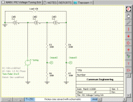
See how the voltage oscillation effects the results differently. If you change the value of any of the resistors the output also changes. So you could know by training what the resistors values are... 8)

Note: Specifically look carefully that when things are in balance at 3.2 volts everywhere the voltage divider results are the same. As you swing high and low from 3.2 volts you get the distortion from the "Loading Effect". It's from the distortion that you can actually get your data. You turn a "negative" (the distortion) into a "positive".
 

Attachments

  • Circuit Tuning Diagram.gif
    Circuit Tuning Diagram.gif
    15.5 KB · Views: 4,254
My point is that voltage dividers do not give accurate results when they are in series and the cells become imbalanced. Unless my simulation routine is wrong (doubtful) the effects of a series of cells and a series of voltage dividers is that some sort of cross influence "Loading Effect" takes place when things get imbalanced. The simple direct multiplication (one dimensional) will not work. It just won't... otherwise people would have probably figured that out a long time ago and no one would have ever invented the Differential Amplifier.

well thats where you made your error the dividers still divide the voltage seen at R1 by the same amount no matter what the voltage is, you dont need to worry about the loading effect, that is if the output from the divider is going to something of low impedance, which its not, the ADC has an input impedance of over 1M. i made up a schematic to show you how this really does work.

cell 1 good as is 3.12V

for cell2:
3.18 * 2 = 6.36
cell 2 = 6.36 - 3.12 = 3.24

for cell3:
3.17 * 3 = 9.51
cell3 = 9.51 - (3.12 + 3.24) = 3.15

do you see yet?, but this is all pointless as this way to get the cell voltages is flawed because of the multiplied ADC error.
 

Attachments

  • div.jpg
    88.8 KB · Views: 2,706
dirty_d said:
for cell3:
3.17 * 3 = 9.51
cell3 = 9.51 - (3.12 + 3.24) = 3.15

do you see yet?, but this is all pointless as this way to get the cell voltages is flawed because of the multiplied ADC error.
But my point is that if you knew with high precision the values of the resistors then maybe using the same sort of calculation (which I think is nice because it's simple) you might actually be able to do this:

for cell3:
3.17 * 3.0140588 = 9.554566396
cell3 = 9.554566396 - (3.xxxxxxx + 3.xxxxxxxx) = 3.xxxxxxxx

...or something like that. My point is the if you hold your precision all the way through your calculation then you will be fine.


And it looks like the "Loading Effect" does not cause this imbalance after all. (correction, my guess was not right)
 
safe, yes exactly thats what you do, you use the actual amount the voltage gets divided by, thats what taht array was for in one of my previous posts, you would use this in C:
float dividers[] = {1.00f, 2.05f, 3.12f, 4.02f, 5.11f, 6.08f};

you still have the problem of the ADC error though, which is increasingly more significant with the number of cells, if you use differential multipliers, the ADC error is at the minimum no matter how many cells.
 
dirty_d said:
safe, yes exactly thats what you do, you use the actual amount the voltage gets divided by, thats what taht array was for in one of my previous posts, you would use this in C:
float dividers[] = {1.00f, 2.05f, 3.12f, 4.02f, 5.11f, 6.08f};
In the higher level languages there are math packages that deal specifically with this issue.

http://www.vni.com/company/corp.php

I used to work for these guys as a traveling techie. Way too much airline travel for my tastes and they were forced to fire me when one time they asked me to fly somewhere and I just said "No". Next day I was fired.... they were in the right... what can I say... it was not my kind of job. :cry:


dirty_d said:
you still have the problem of the ADC error though, which is increasingly more significant with the number of cells, if you use differential multipliers, the ADC error is at the minimum no matter how many cells.
But with tuning along each branch you could reduce the error down to next to nothing. By stimulating each branch one at a time you eliminate the propagation uncertainties. To my knowledge these input pins can also work as output pins so you could read and write to them. All you have to do it run a tuning routine that writes a specific voltage (or a range) to a pin as output then measure what you get back on the other pins.

:arrow: Besides... the whole point of this exercise is to use the power of the PIC to create a voltage measuring (and later balancing) system at a really low price and with lower external complexity. Using resistors and creating a tuning startup routine would be delivering on that...
 
safe said:
But with tuning along each branch you could reduce the error down to next to nothing. By stimulating each branch one at a time you eliminate the propagation uncertainties.

the error im talking about isn't from any of the analog circuitry, its from the microcontrollers design, even if you get the analog circuitry absolutely perfect. the whole system is still only as good as the ADC, there are way in software to reduce the ADC gain and offset error but its usually impractical as its already very close (9.8mV for mine) you can reduce some of the quantization error by oversampling. but still this is not the error im talking about, even if you get an acceptable error like +-2mV from the ADC, that 2mV error is going to be multiplied by 10 when you are calculating the 10th cell assuming the divider is exactly 10:1. if that amount if error is good enough for your system then use it this is a simple way to make the BMS and its cheap but it just doesn't seem ideal to me and for a little more money you could make it much better.
 
dirty_d said:
...that 2mV error is going to be multiplied by 10 when you are calculating the 10th cell assuming the divider is exactly 10:1.
But again my point was that you don't just pull an integer out of the blue and use that as your calculation value. If you knew with precision all the resistors in the system (through some sort of tuning routine run before use) then your precision might allow you to multiply by 10.0115 rather than the simple 10. This added precision of knowing the resistors and the system will compensate for the errors. It should work... as long as the software is written correctly the precision should be good enough. Just how much precision do you really need anyway? It seems to me that 0.1 volt is close enough, so as long as the worst case was less than that it would be okay.

:arrow: Why spend more money when you could write better software instead?


But despite all this, there's still the fact that a single PIC solution can only deal with at most 14 cells. So for all the people that want to go 48 volts and above this voltage divider solution would not work without a multiplexer, so I'm leaving that open as a reality that has to be looked at.

:shock: I could see development done on a super simple minimalistic 14 cell or less BMS system using a PIC. If you are using 36 volts it's all you would need...
 
With the shunts, you don't want to do cell balancing, per se. That would simply drag down the level of the stronger cells to that of the weakest. It has been my experience, with a123 cells at least, that eventually all the cells will end up at different levels. Paralleling them will help normalize the differences, but you will still end up having some difference between parallel bolcks that are in series. The bottomline is, it doesn't matter. What you want to do to get the maximum life out of the cells is simply to make sure each cell/block of cells can a 100% charge, and you want to make sure that each cell/block can't be over-discharged. A 100% charge for one might be different than a 100% charge for another, and it might take one cell longer to get to that point than another. The best way to ensure that each cell/block can get a "full" charge, is to use an individual CC/CV charger on each cell. This would let each cell get a constant max current while the voltage rises. Because it becomes harder and harder for a cell to accept current as it gets fuller, the voltage will rise. Once the cell gets to about 3.65V, the charger holds it there. With the voltage held there, the cell can't accept as much current so the current starts to drop. When the current drops to about 100-200 mA, the cell is about as full as it can get.

A bulk CC/CV charger would work fine if all the cells had exactly the same capacities, internal resistances and thermal characteristics, but they don't. What happens is that as a cell charges, the voltage will rise at a steady rate. Once it gets above about 3.65V-3.70V, however, the rate the voltage rises goes up significantly. It can hit 4.0V in a matter of seconds. If you have a few stronger cells that reach this point first, it will cause the charger to hit the CV limit.
these stronger cells will then start reducing the current they take in. Since all the current has to go through all the cells, all the time, the weaker/slower cells can't ever get to their own "full" levels. If you then try and balance the cells, the stronger ones are bleed off and dragged down to the level of the lowest one. This is exactly how the cheap Chinese BMS boards that come with the so-called "duct tape" packs work.

What the shunts do is give us the best of both worlds. Each cell can get a full charge, at its own pace, but a bulk charger/supply can be used. What happens is that the voltage for each cell is "clamped" at around 3.65V, which will cause it to start reducing the current it will accept. Whatever it doesn't "use", will be conducted through the shunt. The net result is that the next cell in series will have the full amount of current available. So in effect what you get is a single bulk CC supply with individual CV control.

In any case, if you don't use a shunt regulator chip, like the LM431, which is really nothing more than a programmable zener diode, the program would need to peroform this function for each channel, and then drive the opto/darlington combo for each. That means you need a separate line that needs to go to each channel, just to control the shunt, You also need separate lines for whatever is used to sense the voltage (diff amp, divider network, etc...). Running traces for all these takes up lots of real estate and I'm not sure it gets you all that much. The LM431 is about $0.11 at Mouser (512-FAN431LZXA). I'm a big fan of distributed processing, and I think that unless you are going to save big chunks of money, it may not make sense to have the micro do everything.

-- Gary
 
dirty_d said:
you still don't get it i give up, lol.

Really safe, don't start thowing a bunch of abstract math crap in here. It's not helping.
We do know what we're doing.


Gary, I agree with your points. I did want to go through the exercise to see what the limitations are and to see which approach winds up costing less overall. The fact that the PIC based unit can measure the high and low voltage points with the same hardware was attractive. Also being able to tweak the set points for different chemistry seemed like a nice feature. One BMS that works for Co, Mn, FePO4 and whatever they roll out next year.
There would be a lot of possiblities for 'bells and whistles' with the PIC approach, like individual cell voltage displays, bad cell identification, fuel gauge, it goes on and on...

OK, it seems like single dividers on each tap going into the ADC will yield reasonably crappy accuracy, even if we correct things in software. We still haven't answered what is "good enough" for the accuracy though.

A two channel MUX feeding a differential amp solves a lot of the accuracy issues, but adds expense.

The PIC16F88x has an incredible amount of stuff crammed into a chip that only costs $3.50.
Optocouplers are the easiest way to send the shunt signals for balancing, and are cheap enough. The larger PICs seem to have plenty of outputs to drive these.
 
Gary,

Thanks for explaning shunt idea. But I still don't understand why is it advantageous as compared to china balancer alternative. I'll go with example. Let's say my pack has 10S cells. 9 of them are 2.3Ah and one is 1.7Ah.

Chinese charger/balancer will charge every cell to 1.7Ah, so my total energy is 1.7*33 = 57Wh

Your charger will charge each cell to the maximum, which is 2.3Ah for 9 cells and 1.7Ah for weaker one. Total 74Wh in the pack.

Now when I discharge the pack - after I've drawn 1.7Ah from it, my weak cell will drop bellow 2V and, while other still have 0.6Ah in them. I'm still unable to draw more than 57Wh out of my pack.

Thanks!
 
Now I feel like I have found the holy grail of cell measurement! Texas instruments INA132. Why it's cool:
- Differential unity gain amp. Just hook in the cells and measure voltage on the output pin. No external resistors.
- Can take up to 36V supply, so 10S pack is no problem. No voltage dividers. No resistor errors. No impedance problems. I'm a bit confused about them saying that inputs can go as high as 80V - is it working voltage or survival?
- 0.2 mA power draw so won't discharge batteries
- Cost $1 in large quantities.

http://focus.ti.com/lit/ds/symlink/ina132.pdf

Now the bad news: PDIP package is discontinued and SOIC are out of stock/expensive everywhere I looked ($3 for single chips).
There's two channel version too INA2132, and many other similar diff op amps. But the others are a bit worse in one way or another (need more power, need external components, etc).
 
tomv, if the pack doesn't do anything to balance the pack then the cells will just keep getting more and more out of balance and your 1.7AH will turn to 1.6Ah and just keep getting lower, that cell is probably bad if its that far off anyway. also if you charge each cell to 100% the average voltage of the whole pack during discharge will be higher than if you just charge each one to 1.7Ah so you do gain some energy capacity.
 
dirty_d: I'm not suggesting not to balance the pack at all. I'm trying to figure out the merits of shunt bypass vs disipatting small current on a small resistor (chinese method).

Advantage #1
As you mentioned, fully charged cells give more voltage so capacity is slightly higher, depending on chemistry. A123 cells have very flat discharge though.

Advantage #2:
The shunt method can charge faster. In my example 1.7Ah cell would reach 3.7V much sooner than others and charging current would have to be reduced. If it was shunt bypassed, the strong cells can continue at their full pace. It's hard to tell how bgi the speed advantage would be (if any), assuming we cut charging when all cells reach 1.7Ah

Disadvantage #1:
More and bigger components. Optocouple + big FET/BJT/darlington + big shunt + heatsink vs optocouple and small 1/2W resistor.
 
there is also the choice of the microcontroller to use, microchip PIC and amtel AVR seem to be the most popular two, ive only just started using AVRs and they are pretty awesome and easy to use, ive never used a PIC so i don't know if there is an advantage. so i set out to find the differences between the two i went on irc in freenode #electronics channel and asked what advantages each has over the other. i got some semi-useful answers such as:

"pic users are smelly old men with dirty beards."
"avr users are all dashingly handsome and have hot girlfriends.
"PIC has only one register, AVR has 32, so it's easier to program in ASM, less moving around"
"but the fastest AVR i know is 20MHz, the fastest PIC i heard of was around 40MHz"
"most instructions on AVR are one cycle, but there are a few with more than one"
"solely judging from my experiences watching this channel, pic makes you say things like "aww f%&^.. work you POS,, f*&!" and "OOh! they gve me bags of chips for free!".. avr makes you say things like "Woot! it works!" and "I wish the f'ers would give me free samples"

i looked online for some more in depth information:

"Common misperceptions: Some people think the fastest Microchip pic (20 MHz 4:1 pipeline) is as fast as the fastest Atmel avr (20 MHz 1:1 pipeline). They are wrong. The pic is actually processing instructions at 5 mips and the avr is at just under 20 mips. Also, the avr instruction set is larger, so in many cases, it is getting more done in fewer cycles."

"It seems that AVR resources are more fully featured. The PIC seems
spartan by comparison. For example, timers can count up or down on
the AVR. Just up (int on overflow) on the PIC. a small matter to
adjust for but this is but one example. PWM on the AVR is very full
featured for another example."

"choice of flash PICs is much wider than AVRs (forget non-flash PICs)"

"free GCC C compiler for AVRs"

i couldn't really find a direct MCU to MCU comparison but it seems like the AVRs are faster, the max clock for AVR's is 20Mhz with 1 instruction per cycle, and the PIC's max clock is 40Mhz with 1 instruction every 4 cycles, so even though the PIC clock is faster the AVR executes more instructions per second. it also seems like its a lot easier to program for an avr, there are more registers and the on-board peripherals seem to have more powerful features. avr has at least 2 free assemblers and c compilers, you can get the pic c compiler for free but if you want to enable optimization you need to buy it.

anyone have experience with both?
 
:lol: It's just funny for me that I went through the long process of proving my point and after all the counter arguments were handled and the "grand conclusion" of it being a success was achieved everyone seems to want to run away from it.

Why even use a PIC when you are afraid of using software and advanced numerical analysis techniques with it?

Isn't that the whole point of software?

Strange.... very strange... however, my coming from a software development background does tend to make me more comfortable with the software side so it doesn't scare me as much. (I love solving those kinds of problems)

Seriously folks... you could use nothing but dirt cheap resistors and some brains and get the job done.

Oh well... :roll:


I would have rather heard something like:

"I just don't know enough about how to preserve precision within my software and don't really want to learn that and would prefer to do things the way I know how to do it... you know... the electrical engineers approach to things."

...at least that's being honest.
8)
 
no, you cant. unless 0.1V+ is an ok error for you then fine, but if you want < 10mV accuracy that just will not work. if you have already solved the problem and know how to get good accuracy with that then show us. show some work and not just talk. write a simple program showing how this will work that simulates the error from the adc and correct for it, mind you the adc error wont be consistent, it can be +- 9.8mV or anywhere in between, lets see some proof :D
 
dirty_d said:
no, you cant. unless 0.1V+ is an ok error for you then fine
:arrow: That's close enough to trigger a LVC isn't it?

I don't see the need for so much precision... if your goal is to do something like create a LVC then all you need is some resistors, a PIC and some some software. You could have a signal wire that went to your throttle and pulled it down as the weakest cell approached the limit. If you need a little safety you set the limit at 2.6V rather than 2.5V so that in a worst case scenario you cut out a little ahead of time.

I'm not saying that the software would be easy to write, but I'm saying that I can see a way to do it and have presented it here. You just tune the system as part of a startup routine. (as I showed over many posts) It will take a little math, but that's fun to do. :)

Let's agree that it's potentially "possible" but may be not something that anyone is interested in doing and then move on. Don't say the idea is "impossible" without really thinking about if it really is correct to say so because then I have to defend it's potential. :wink:


I can remember software development projects where things seemed bleak and impossible in the beginning and somewhere in the middle you all of a sudden "got it" and once you hit that point you KNEW that it was downhill all the way home after that. I don't think this hill climb would be that hard, but it might take a few weeks of work to even get to the critical point of seeing it.

Note: Some software packages can extend the number of bits of accuracy to whatever size you want. So you could use 50 bit accuracy if you wanted. The size of the data that you do operations with is not limited to the number of bits that the data is entered as being. So I hope you've realized this... you don't do all your math using 10 bits, doing that will DEFINITELY mean you lose accuracy. These routines can come in the "C" language and tend to be portable.
 
A few more cool amplifiers: AD629 and INA117. Both can take 200V+ inputs directly and give clean low voltage VIN1-VIN2. This is twice less components then resistor dividers and far more precise than even divider/mux/amp combo. The downside is cost, in single units amps go for $5-$8. Nice bms than would be $100+, more than the batteries! Still, I'm thinking to just go with those for simplicity/ease of use/precision/piece of mind.

I'm thinking to use AD627 as my current sense amp (gain adjusts with just one resistor).

If you can work with SOIC packages then there are a few more, like INA148, AD628.
 
C Programming with the Microchip PIC

http://tutor.al-williams.com/picc1.htm

16f8x.gif


If you don't like assembly language, you might be tempted to switch to a high level language like C. I've often said that the PIC 16F family is not well-suited for C. However, there are C compilers available and they do work. This tutorial will show you how to get started with the open source SDCC compiler and our APP-II board. I'll assume you know C already -- this tutorial just covers the SDCC and APP-II specific issues.

My Comment: Using a "C" language compiler for the PIC means that as long as there is enough memory space on the chip you can add extra libraries that can do all the high precision math you might need to do. I've programmed in assembly and "C" and Java (and several others) and you always want to go with the highest language level possible because it's easier. Modern optimizing compilers are so good that it's a rare assembly language programmer that can beat the power of the optimization routines. (it's almost impossible to beat them these days)
 
WIZ-C Professional

Floating Point Support

The FED C Compilers (WIZ-C Professional and AVIDICY) now supports a 4 byte float type to IEEE standards. The float type supports numbers from approx +/-10-37 to +/-10+38, and has full arithmetic and cast to/from integer support in line with ANSI C.

http://www.fored.co.uk/html/float.HTM

Banner07.gif
 
Back
Top