A PIC based Battery Management System

rf said:
There's an elegant solution out there somewhere ... I can smell it.
Well I think the Voltage Divider solution with software correction is the way to go. You can't beat the price of resistors and with software you can automatically calibrate to adjust for temperature variations. The only hard part is figuring out how to test the circuitry... you would need to run some routine that would test the response of each branch and then be smart enough to make sense of it all. Since I've got a cold right now my brain is not up to the task... :?
 
Well, here's what I was missing. I was going to float the logic ground from the analog ground to eliminate the mux over voltage problem. However, the floating ground might create a problem on the current bypass during charging; don't know enough to say. $5/mux isn't bad - that's only 63 cents per cell. $15 - OK, more, but not earth shaking. Presumably this is going to protect a pack that costs $1000+ - penny wise and pound foolish?

Another possibility with differing ground potentials. Can the mux chips (those that will take a 40V voltage level) - is that plus or minus 40V? If so, could you tie logic ground to the middle of the pack? Again, same (perhaps slightly different) problem on the charge current bypass.

I do like the one uP per cell; that's what we're doing on the TS. However, If $5/cell is too much, I think you're going to be hard pressed to deliver a solution, considering fab costs (unless you've got volume).
 
Patrick said:
I do like the one uP per cell; that's what we're doing on the TS. However, If $5/cell is too much, I think you're going to be hard pressed to deliver a solution, considering fab costs (unless you've got high volume).
The thinking has been that if you create a PIC based solution that you move as much of the logic you need to the PIC and away from components. Software is free once created. At $5 per cell and 16 cells you are looking at $80 just for the component parts. That just seems like too much. If instead you could use simple resistors and a voltage divider arrangement (that somehow calibrates and corrects itself) you shave almost $80 off of the cost of the product.
 
safe said:
The thinking has been that if you create a PIC based solution that you move as much of the logic you need to the PIC and away from components.

Err, no, that's been your thinking. What I was saying was $5 (actually ten for two chips) per 16 batteries, or 63 cents per battery. There are some things you want to do in software, and there are others that are more appropriate in hardware. For instance, current shunts are made of a specific metal that has almost zero thermal resistance drift. Shunts can be expensive, but much better to do that than use an MCU and temperature sensor to "model" the thermal response; it might be cheaper, but it would be almost insane
 
Okay, Fetcher's original idea is making a lot more sense just now ... I'm feeling slightly less dense today. Let me see if I can prove that theory wrong ...

Simple case:

1. The microcontroller (MCU) has some built-in analog to digital converters (ADC) with a range of 0 to 5 volts.
2. Connect an analog multiplexer (with as many channels as your battery has cells) to an ADC input. (This allows the MCU to select one cell at a time to measure.)
3. Connect battery ground to ADC ground.
4. Connect each cell's positive terminal to a separate multiplexer input through resistor(s) that reduce maximum battery voltage to 5 volts or less.
5. Hardware done.
6. Read from cell #1 and get it's, more or less, true voltage.
7. Read from cell #2, subtract cell #1's reading to obtain #2's voltage.
8. Read from cell #3, subtract cell #2's reading (not it's voltage) to obtain #3's voltage.
9. etc ...
10. Assuming cheap parts, each channel will need to be aligned once to set offset and scaling so the MCU can display true voltage. The offset and scaling factors become part of the MCU's program.

Accuracy will be the issue. How do you reduce the voltage of each successive cell so that it can NEVER overshoot the 5-volt limit of the multiplexer? Lower/safer is fine -- except that you lose resolution and accuracy. We don't need tons of accuracy, but we probably don't want to be reading 5-volts from a 100-volt scale either.

Contrary to what some have suggested, this isn't a ladder. To measure any one cell takes only two readings, not a succession of them.

Thoughts?

Richard
 
rf said:
How do you reduce the voltage of each successive cell so that it can NEVER overshoot the 5-volt limit of the multiplexer?
Darn, you beat me too it... I was thinking the same thing. This was actually covered about 5-6 pages ago in the thread.

Our "circular logic" seems to be following this line of reasoning:

:arrow: Step One: Good Comparators are too expensive.
:arrow: Step Two: Use A MUX... then it's cheaper.
:arrow: Step Three: MUX's can't deal with high common mode voltage.
:arrow: Step Four: Throw in some Optocouplers.
:arrow: Step Five: Question why we do any of this in the first place. :lol:
 
One PIC, One Opto, One Cell

:idea: Okay, how about this...

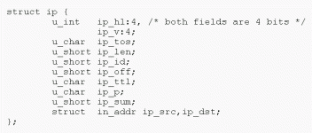
Use a single PIC that has a very low power requirement and is able to be run on as low as 2.5 volts. Wire this PIC so that it's source voltage is the cell itself and nothing more. Now in the logic output side you place a single optocoupler to isolate the data stream so that you can create communication. Use the internet model for communication, so set a random timer on the PIC. (make it's seed value based on the cell voltage, this will ensure that deviations exist all the time) Now out of every million cycles of the PIC pick some place in the middle to broadcast your PIC's identity and data in a single packet. You might as well use the IP protocol since it's everywhere. If there is a collision you throw that data away. Maybe this part is not the best, but you get the idea. Anything on that bus could know what is going on just by listening.

So the PIC gets bound to the cell and the data then is sent through the optocoupler... it's another thought... :?

Below is the IP protocol in the "C" language:


http://en.wikipedia.org/wiki/Ip_%28struct%29

This would basically make your battery an internet device... :p
 

Attachments

  • ip protocol.gif
    ip protocol.gif
    4.3 KB · Views: 2,797
Patrick said:
I do like the one uP per cell; that's what we're doing on the TS. However, If $5/cell is too much, I think you're going to be hard pressed to deliver a solution, considering fab costs (unless you've got volume).


What are you doing there? How do they communicate? Got shunts?

So, one uP per cell is one extreme, and using a big MUX and a single uP is the other extreme.
I'm starting to think that somewhere in between might be the optimum. One uP that handles 2 or 4 cells keeps the voltage differentials reasonable and allows uP's with multiple A/D inputs to watch all the voltages with no MUX.

In this configuration, I'm thinking instead of communicating the voltages out to a "master processor", each 2 or 4 cell unit would behave autonomously and just have two optos for outputting "any cell too low" and "any cell too high" signals to a common circuit that cuts the discharge or charge. This way you could gang together as many 4 channel units as desired.

If you actually want to send voltage data over something like a I2C buss, is that hard to do? You'd need bidrectional optos on each one?
 
Don't know about doing isolated I2C with optos, but Analog Devices has a nifty chip just for this. http://www.analog.com/en/prod/0,2877,ADuM1250,00.html It's prolly ~$6 in the volumes we'd buy. Rs-232 would work if the data is modified to always send an equal number of zeros and ones, and idle at some mid value. Then transformer coupling or AC coupling could be used from module to module. (with a ring topology? just pass a one big packet of cell voltages from module to module around the ring?)

My 2 cents,
Marty
 
fechter said:
I'm thinking instead of communicating the voltages out to a "master processor", each 2 or 4 cell unit would behave autonomously and just have two optos for outputting "any cell too low" and "any cell too high" signals to a common circuit that cuts the discharge or charge. This way you could gang together as many 4 channel units as desired.
:arrow: Well then you are making 12 volt units.

I have a feeling that this is the ultimate path that things will go anyway because there is always a strong "backwards compatibility" argument in anything you get involved in.

I'd love to be able to simply buy 12 volt batteries with built in computerized circuitry that keeps the battery secure. Maybe we should look to doing that idea?

Let's assume:

:arrow: Units of 4 cells making 12 volt battery units.
:arrow: Each unit needs to do balancing within itself.
:arrow: Each unit needs to do low and high voltage cutoffs.
:arrow: Units need to be tolerant of being chained in series.

...of course in the future this will be given away for next to free with the cells. However, given todays prices you pay 3x for the same cells in such a package.

Let's just assume that outside the unit itself there is no communication at all.


By choosing this path we would be molding our future towards the likely actual future the rest of the world will accept. Our efforts today will mean that tomorrow there will be less adaptation to be done. We might want to standardize on an existing battery shape... like a 12V - 18 Ah cell or something that is a standard in the hopes that the future will agree with us... :)

sla-17-12.gif
file.php
 
safe said:
rf said:
How do you reduce the voltage of each successive cell so that it can NEVER overshoot the 5-volt limit of the multiplexer?
Darn, you beat me too it... I was thinking the same thing. This was actually covered about 5-6 pages ago in the thread.

Our "circular logic" seems to be following this line of reasoning:

:arrow: Step One: Good Comparators are too expensive.
:arrow: Step Two: Use A MUX... then it's cheaper.
:arrow: Step Three: MUX's can't deal with high common mode voltage.
:arrow: Step Four: Throw in some Optocouplers.
:arrow: Step Five: Question why we do any of this in the first place. :lol:

Yes, I just reread the thread before my last post. I think Fetcher may have had it right from the start. One MCU and a handful of resistors is all you need. (And a mux if your MCU doesn't have enough ADCs.)

I don't think the optos are necessary either.

Scaling the max voltage of the pack down to 5-volts is all that's necessary. The standard 10-bit ADC on the MCU should yield slightly better than 0.1-volt steps for a pack voltage of 100-volts. That's probably a workable resolution. A reasonably accurate, real time voltage measurement of each cell.

LVC Done! For less than $15 worth of parts, total. Charging control will take a little more hardware.

Fetcher, how do I reduce (divide) 100-volts to 5-volts? (+- 20%)

I can whip up a test setup on one of my ATmega168 boards in an evening. Pretty sure I have some cheap mux chips in my parts box.

I think I've been over-thinking this thing all along.

Richard
 
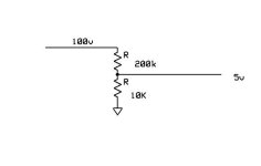
A divider is pretty easy. The ratio of voltages is the inverse of the ratio of resistances.

To go from 100v to 5v, it would look something like this:
Resistor divider.jpg

One drawback of this arrangement is the divider resistors are always draining the batteries (although at a very low rate)..

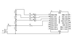
Another crazy idea I had would be to add zener diodes to the tap wires to drop the voltage down into the under 5v range. This way, the drain on the batteries will be negligible when the processor is asleep or looking at another input. There's still the problem of activating the shunt for the higher cells. Either optocouplers or some kind of level shift will be needed to take the output from the uP to activate the shunts.
PIC16F818 front end.jpg
 
fechter said:
Another crazy idea I had would be to add zener diodes to the tap wires to drop the voltage down into the under 5v range. This way, the drain on the batteries will be negligible when the processor is asleep or looking at another input. [...]


Cool. Will the zeners divide the voltage linearly?


Richard
 
Fetcher always sends me searching to learn more stuff.

Maybe I'm missing something, but it seems at some point the difference between n*2.1V and n*3.65V will exceed the allowable voltage on an input pin. For a pin with 0V-5V, you can only do 3 cells to a single chip. So you would either need one set of ADC pins set up with zeners to detect for low voltage cutoff, and a different set of ADC inputs to detect for the high voltage side of things.

Example: on the 5th cell, a low voltage signal should kick in when the difference between the cells is only 2.1V. The positive end of the cell will be around 10.5V, so a 10.4V zener drops this into the usable range on the input pin (0.1V in this case) and the software compares that to other measurements and can flag up a low voltage condition. When charging, the positive end of that cell will climb to 18.25V, so the 10.4V zener only brings it down to 7.85V. If that exceeds your ADC input limits it's no good.

Maybe there's another voltage drop across the other resistors shown in the diagram and that makes this feasible? Like I said, I'm probably missing something.
 
fechter said:
Patrick said:
I do like the one uP per cell; that's what we're doing on the TS. However, If $5/cell is too much, I think you're going to be hard pressed to deliver a solution, considering fab costs (unless you've got volume).


What are you doing there? How do they communicate? Got shunts?

One MCU per cell. The shunt is just a resistive load - maybe 10 watts, but that could be scaled - haven't thought about the implications of that. Designed specifically for the TS LFP 40,60 and 90 Ah cells physically; on the logic side, it's all programmable, so could fit any cells parameters. They communicate through CANbus. Bench testing well from what I heard.

Again, designed for large format cells. Large cells are expensive (let's say $200 each) so spending an extra $10/cell is fine. This kind of design doesn't scale down very well - kinda useless at the $15/cell that LifeBatt will become soon. That's one issue that hasn't been addressed in this thread - what are the design parameters? It's kind of mental masturbation when you don't figure in capacity, cost, life span, current loads, charge rates, etc. Don't get me wrong - this is a great thread, but it's not product engineering.

This is why Bob and Garys' solution works well, and came to LiFe so quickly - they had a specific product they were designing for, and could set "reasonable" values where there was variability. Personally, I'd like to see a 20 amp charge capability on their solution. And I'm sure others have their own desires. So keep it up, but remember that any design needs specific goals to meet.
 
Patrick said:
what are the design parameters?
I've asked the same question before. It's been answered and modified over the course of the thread. This isn't a thread that needs "urgent" action to deliver a product it's more about thinking of all the options.

My contribution to charging parameters is that we should seek to achieve the goal of the standard house plug. The typical house plug at 120AC can deliver about 1000W of power and not much more. Translate that to our cells and that means that for something like a 48V pack you should be able to charge at:

48V / 3.2V = 15 cells

1000W / 15 = 67 Watts per cell

Charging at 4.25V means you can deliver 15.7 Amps to a cell.

So our goals for charging should be to approach the upper limit of about 15 amps per cell or 20 amps if you were to be using a 36V pack, whatever it takes to equal 1000 watts in total so the fuse doesn't blow at the house.

Your cells should ideally charge at about 1C or less so retroactively you would want to have 15Ah or 20Ah cells or larger. Series only, parallel cells should become obsolete as the new cells become more common.
 
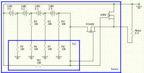
Either "Power" or "Wire"

file.php


Continuing along this theme (which is good) I'm thinking that you skip shunting altogether. You revert back to balancing through the PIC alone which was calculated as being something like only 1% per day. But if balancing is a continuous process running day and night it should do all the work needed to get the job done. (good enough anyway) The PIC runs on the 12 volts that exists within itself and all references would be relative.

So balancing is done ENTIRELY by the PIC at a very slow rate.

Calibration could intitially be done by just measuring the resistors manually and hoping that is "good enough", but eventually I'd prefer self correcting software that would continuously update the accuracy of the resistor values to improve the precision.

As for low voltage or high voltage cutoffs the overall battery acts in one of only two modes... either it's a "Power" device and gives off it's energy or absorbs energy or it's a "Wire" which means it's either too full to accept any more energy or too empty to give away any more.

"Power" or "Wire"

...and that's about it. :)


Parts List:

3-4 Resistors ($0.50 each)
2 FETS ($3 each)
1 PIC ($2 each)
 

Attachments

  • 12 Volt Battery Diagram 001.gif
    12 Volt Battery Diagram 001.gif
    8.5 KB · Views: 2,636
No, I think we still need a shunt for each cell to balance during charging. The PIC can't drain the cells fast enough by itself. I just didn't draw it in.

I also want to avoid having anything in series with the battery string to maintain high current capability. Besides, high current FETs are expensive and get warm.

I can see that the zener arrangement won't really work for more than about 3 cells due to the voltage change. The zener simply drops the voltage by a fixed amount to bring it within range of the A/D input (0 to 5v).

A one PIC per cell concept is interesting, but I don't know how you can interface to a CAN or I2C bus with a voltage offset unless you use optocouplers. To be really handy, it would be necessary to communicate both ways to calibrate the individual cell voltage measurements and program the set points for charge and discharge. Some of the 'dumber' PICs are very cheap however.

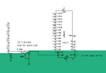
One problem with the 16 channel MUX is the drain caused by the divider resistors. By using a high voltage MUX, there won't be much drain when a channel is open, thus solving that problem, but high voltage MUX chips are expensive.

If we want to use a cheap 5v MUX and use higher resistances for the dividers to drop the drain current, then the A/D will not work properly because its sample and hold capacitor won't charge fast enough through the higher resistance. One possible workaround for this would be to use a small capacitor across the bottom part of each divider to supply a higher current to the A/D when it gets sampled. This way, we could use 1meg or maybe even 10meg divider resistors to get the total drain down to the microamp range and still supply the A/D input with enough current to get a fast sample.

This arrangement would also filter the voltages from the cells, which might be a good thing. The actual cell voltages are not changing very quickly, so lots of filtering shouldn't be a problem.
MUX input divider.jpg
 
fechter said:
No, I think we still need a shunt for each cell to balance during charging. The PIC can't drain the cells fast enough by itself.
Let's review that again... it's been talked about once, but I'd like to take another look at it because if the PIC was used within a 12V (4 cells) battery then everything works pretty well together. (and it's cheap)

So a PIC pin can handle from 20mA to 40mA of current and so this is the way you could balance the cells. From my understanding (after reading on some of the RC websites) the LiFePO4 tends to stay pretty balanced once they are balanced. So during the charging phase you don't need to do that much and could live with next to no balancing during the short period that charging takes place. (less than an hour if we live up to our 1C charging "ideal")

This means we need to think in terms of "watts per day" or something similiar because the PIC is on all the time and constantly checking things and doing balancing where needed.

Let's assume a 30mA balancing current.

And let's assume that each 3.2 cell is 20Ah in capacity.

:arrow: How many hours does it take to balance the cells?

If the worst case scenario is an imbalance of 5% then we need to be able to transfer a total capacity of:

3.2v * 20ah * 5% = 3.2wh (the total imbalance)

If we can balance at 3.2v * 30mA = 0.096w

Then in order to complete the balancing it will take:

3.2wh / 0.096w = 33.3 hours

So in about a day we would expect the cells to all be in balance and on the next recharge we would expect progressively less and less balancing to be needed assuming that none of the cells are defective or severely different in which case the balancing would be more frequent.


The "bottom line" is that the PIC seems adequate to establish a level set of four cells that make up 12 volts. You could overcome the high powered charging if it went out of balance but I don't think we want to do that...

Why balance during the charging phase?

It's better to just wait and do it overnight.
 
safe said:
Calibration could intitially be done by just measuring the resistors manually and hoping that is "good enough", but eventually I'd prefer self correcting software that would continuously update the accuracy of the resistor values to improve the precision.

You're thinking too discretely.

You don't measure the resistors. You don't even care if the resistors are accurate. You set everything up and measure each cell's voltage ONE TIME!
And tell the MCU the levels you read. The MCU computes the difference. Now it knows how much to adjust for each one and handles it behind the scenes. (This assumes the circuitry is linear. Otherwise two measurements may be necessary.)

Simple resistors in a simple circuit shouldn't change over time. Not enough to matter.

Richard
 
fechter said:
[...]
I can see that the zener arrangement won't really work for more than about 3 cells due to the voltage change. The zener simply drops the voltage by a fixed amount to bring it within range of the A/D input (0 to 5v).
Would zeners be more or less linear like the resistor network?

fechter said:
A one PIC per cell concept is interesting, but I don't know how you can interface to a CAN or I2C bus with a voltage offset unless you use optocouplers. To be really handy, it would be necessary to communicate both ways to calibrate the individual cell voltage measurements and program the set points for charge and discharge. Some of the 'dumber' PICs are very cheap however.
I agree. Even with the cheapest chips it sounds like overkill. One MCU is good. More than one raises complexity enormously. Especially when you expect them to talk to each other.

fechter said:
One problem with the 16 channel MUX is the drain caused by the divider resistors. By using a high voltage MUX, there won't be much drain when a channel is open, thus solving that problem, but high voltage MUX chips are expensive.
What about putting the voltage divider between the MUX and the MCU? Then you only need one resistor network. And it can be disconnected from the cells by disabling the MUX. Precision at the ADC becomes an issue, but not necessarily insurmountable.

fechter said:
If we want to use a cheap 5v MUX and use higher resistances for the dividers to drop the drain current, then the A/D will not work properly because its sample and hold capacitor won't charge fast enough through the higher resistance. One possible workaround for this would be to use a small capacitor across the bottom part of each divider to supply a higher current to the A/D when it gets sampled. This way, we could use 1meg or maybe even 10meg divider resistors to get the total drain down to the microamp range and still supply the A/D input with enough current to get a fast sample.

This arrangement would also filter the voltages from the cells, which might be a good thing. The actual cell voltages are not changing very quickly, so lots of filtering shouldn't be a problem.
That sounds very interesting.

I think we're getting somewhere!

Richard
 
A resistor divider will linearly divide the voltage by a fixed factor. A zener subtracts a fixed voltage.
Zeners are sort of a pain sometimes, and it may be difficult to get the exact values you want.

MUXing before the divider would require the MUX handle the full pack voltage. I have not seen any devices that can do that. Even the HV ones are only good for a 5v signal, they will just not blow up at 70v input. You could make a MUX from discrete photo FETs or analog switch chips, but that would put the parts count way up and the cost too.

They make PICs with 8 analog inputs. Perhaps there are 16 input versions that would eliminate the need for a MUX if the "enhanced" divider setup was used.

At this point, I think it would be good to test the divider setup on a breadboard or something to see if the accuracy is good enough.

The one uP per cell idea is not totally out if each one is like a buck and can handle all the functions for each cell and does not talk (serially) to the others. I'm thinking if it can, in fact, still operate at 2.something volts to 3.65 volts, measure it's own voltage accurately enough, and have two optocoupled outputs to signal LVC and shunt activated, it would make a cool little building block. You'd burn it one time for the desired cutoff voltages. From there, the rest of the circuit would have to be like Gary and Bob's.
 
Hmmm.... after doing a bit more research, I ran across the PIC10F220:
http://ww1.microchip.com/downloads/en/DeviceDoc/PIC10F220222 Data Sheet_41270E.pdf

According to the data sheet, will operate from 2.0v to 5.5v, has an A/D converter (8bit), can source or sink 25ma on the outputs (plenty to activate a shunt and optocouplers)

And it costs $.65 each! (cheaper in high volumes).

Now I think this is becoming a more viable option.... I need to read the datasheet some more.
 
fechter said:
A resistor divider will linearly divide the voltage by a fixed factor. A zener subtracts a fixed voltage.
Zeners are sort of a pain sometimes, and it may be difficult to get the exact values you want.

If the zener subtracts a fixed voltage then perhaps linearity is not a problem. Exact values are unimportant -- we have a computer (MCU) to deal with the fudge factors.

fechter said:
[...]
They make PICs with 8 analog inputs. Perhaps there are 16 input versions that would eliminate the need for a MUX if the "enhanced" divider setup was used.

ATMEL chips are available with 16 ADCs too. Unfortunately, my battery pack has 20 cells to monitor (72-volt A123s) -- with a plan for adding more in the future. Eight channel MUXs are my preference at the moment. Easy to daisy-chain for as many channels/cells as you want.

fechter said:
At this point, I think it would be good to test the divider setup on a breadboard or something to see if the accuracy is good enough.
Will try that shortly. Accuracy is not that important. Consistency is. The MCU is in charge of accuracy.

fechter said:
The one uP per cell idea is not totally out if each one is like a buck and can handle all the functions for each cell and does not talk (serially) to the others. I'm thinking if it can, in fact, still operate at 2.something volts to 3.65 volts, measure it's own voltage accurately enough, and have two optocoupled outputs to signal LVC and shunt activated, it would make a cool little building block. You'd burn it one time for the desired cutoff voltages. From there, the rest of the circuit would have to be like Gary and Bob's.

There are sub-dollar, very low power versions of the ATMEL AVR too. Just feels messier than necessary ... and most of these MCUs do take some glue.

(The AVR consumes substantially less power. If you use the power-down modes judiciously it may not matter so much.)

Richard
 
fechter said:
The one uP per cell idea is not totally out if each one is like a buck and can handle all the functions for each cell and does not talk (serially) to the others. I'm thinking if it can, in fact, still operate at 2.something volts to 3.65 volts, measure it's own voltage accurately enough, and have two optocoupled outputs to signal LVC and shunt activated, it would make a cool little building block. You'd burn it one time for the desired cutoff voltages. From there, the rest of the circuit would have to be like Gary and Bob's.

Okay, I've been staring at these words some more ...

Hmm. Maybe.

But please stop limiting the ability of these MCUs! ``burn it one time for the desired voltage''. ????

Making one tiny MCU field programmable, to any set of on/off voltages will cost you NOTHING. They have onboard EEPROM for long-term storage and extra I/O lines for input. Minimally you can use a few jumpers to select from a list of settings. Or take input, ala push-button and flashing LED, and select any values you want.

Think COMPUTER.

Richard
 
Back
Top