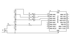
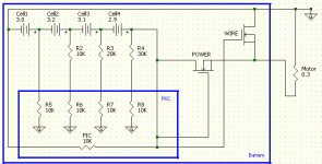
No, I think we still need a shunt for each cell to balance during charging. The PIC can't drain the cells fast enough by itself. I just didn't draw it in.
I also want to avoid having anything in series with the battery string to maintain high current capability. Besides, high current FETs are expensive and get warm.
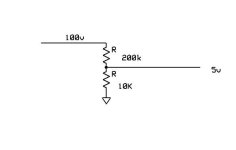
I can see that the zener arrangement won't really work for more than about 3 cells due to the voltage change. The zener simply drops the voltage by a fixed amount to bring it within range of the A/D input (0 to 5v).
A one PIC per cell concept is interesting, but I don't know how you can interface to a CAN or I2C bus with a voltage offset unless you use optocouplers. To be really handy, it would be necessary to communicate both ways to calibrate the individual cell voltage measurements and program the set points for charge and discharge. Some of the 'dumber' PICs are very cheap however.
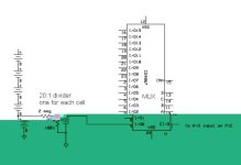
One problem with the 16 channel MUX is the drain caused by the divider resistors. By using a high voltage MUX, there won't be much drain when a channel is open, thus solving that problem, but high voltage MUX chips are expensive.
If we want to use a cheap 5v MUX and use higher resistances for the dividers to drop the drain current, then the A/D will not work properly because its sample and hold capacitor won't charge fast enough through the higher resistance. One possible workaround for this would be to use a small capacitor across the bottom part of each divider to supply a higher current to the A/D when it gets sampled. This way, we could use 1meg or maybe even 10meg divider resistors to get the total drain down to the microamp range and still supply the A/D input with enough current to get a fast sample.
This arrangement would also filter the voltages from the cells, which might be a good thing. The actual cell voltages are not changing very quickly, so lots of filtering shouldn't be a problem.
