A PWM Controller For Each Cell?

Status
Not open for further replies.
ZapPat said:
I see your idea as actually being a chain of totaly seperate PWM circuits, one for each cell. This necessarily implies seperate PWM controllers, FET driver(s), FETs, inductors and capacitors for each cell. As others have noted, this would be most likely be less efficient than regular battery PWM, but mostly it would be VERY very complex in implementation and fabrication.
Cost might be a factor. Efficiency might be a factor.

But I'm focusing on the concept at this point.

The very fact that PWM can take a voltage and current and translate it into a lower voltage and higher current means that you have the freedom to maintain a constant high current across the whole pack even when some of the cells are actually only contributing less than others. It's that weird "fluke" of behavior that captured my imagination and makes this idea interesting.

The PWM "current multiplication" effect has been staring us in the face for all this time and it could possibly be the cure for balancing...
 
Randomly said:
If you can dig up a link or reference to that patent I'd appreciate it, I'm always curious.
This was the patent I saw about six months ago:

http://www.freepatentsonline.com/5793234.html

SUMMARY OF THE INVENTION

To solve the aforementioned problems, it is an object of the present invention to provide a PWM circuit by which the PWM pulses output from multiple channels are set not simultaneously but with a time difference, so that the power consumption is temporally distributed.

...

wherein, the first and second channel output signals have different duty cycles and different set/reset times.

...

In other words, in the PWM circuit for multiple channels according to the present invention, since the output pulses are set or reset at different timing points for the respective channels, the time for power consumption may be more evenly distributed.


So within this patent are all the ideas necessary to do what I've been suggesting.
 
I just wonder if anyone has tried. I know that in the 600A 156V controller we built at Synkromotive, getting the FET's to gate at the same time came into play.. its not hard when you've got everything in one place.....I just wonder how hard it would be in each battery, with all the inductance flying around the gate on the FET?

I know at GE, when i was working on Wind Power, and large AC drives, we used HUGE IGBT's, with a driver card, but we gated them all at the same time via fiber. There isn't much issue if you're gating them at a low frequency, but timing them at higher, inaudible freqencies is a challenge on even the smallest controllers when you have large currents/fields floating around.

Not saying you can't, just saying one on each battery might be kind of hard. Its best to keep the system in one place so you can shield from EMI, keep your gate paths short and the same length/resistance than you would gain by distributed controllers on each battery.

You'd need each "controller" isolated, correctly timed so they all gate at the same time, and a main motherboard to control them, monitor current of each one, monitor voltage of each one, as well as some sort of high speed com bus.
 
safe, PWM doesn't cause "current multiplication", its not even current multiplication, its more like current division since the current is dictated by the load, and the power side of the circuit sees less current at less than 100% duty cycle for a buck converter. to make a cell output a lower voltage but same current as the rest you need an inductor. if you just have a capacitor shorted across a battery do you realize that its only charged at 50% efficiency? im not sure how to show the work, but it just works out like that unless you start charging at the same voltage that the capacitor is at. if you could calculate the RMS current from t=0 to t=considered charged then i guess you could show the energy dissipation due to resistance. if you charge a capacitor through an inductor, the voltage appears across the inductor instead of the capacitor and the current through the capacitor is slowly increased then slowly decreases and you can charge it efficiently.
 
safe said:
In a typical system that does not have any balancing in it the "runt" (weakest) cell will always be strained at the end of the ride. Every ride increases the divergence more and more until the "runt" dies and for many people with soldered packs that means the pack dies. All the remaining cells still have plenty of life left in them, but the one "runt" cell dragged the whole pack down prematurely. (ask DocBass about him getting old recycled drill packs and extracting the useful cells out of them... only one cell need fail and the pack gets recycled)

:arrow: So yes... divergence is not only possible it's expected.

Balancing is the right idea, but it's adding a separate layer on top of the regular PWM system. So in the philosophical sense it's a "hack" done after the main design was completed.

The trick of being able to extract less from the "runts" in terms of voltage and converting that to a higher current afterwards through inductance (PWM style) would allow the weaker cells to be balanced from the start.

There are two different effects going on here, don't confuse them.

Cell balancing during charging is intended to get all cells to the same state of charge. This is needed because different cells can have different rates of self discharge, and there can also be slight differences in the electrochemical 'efficiency' of charging and discharging between cells that unbalance the state of charge in some cells from others. This state of charge unbalance is a slow and relatively small effect compared to the cell capacity but if uncorrected it builds up over time. Even if all the cells have exactly the same capacity, they can still become unbalanced from each other in a pack. Cell balancing circuitry only needs to handle relative small currents and power, 1/10 of an amp is sufficient to do the job. Cell balancing is needed to keep the state of charge 'drift' from accumulating and preventing all the cells from being charged to their full capacity.

A separate issue is difference in capacity between cells. In this case cell balancing does nothing to correct the difference in capacity between cells, it only corrects state of charge imbalance. Your PWM proposal is intended to compensate for difference in cell capacity. The PWM circuitry must be capable of handling the entire power drawn out of the battery pack, since all the power out of the pack flows through it. This means high current FETs, large High current capacitors etc. Also since all the power out of the pack has to flow through your PWM system it is subject to all the losses in that PWM system, which means at least 10%-15% of your battery pack power will now be dissipated as heat in your PWM system. Unless your cell capacities vary by more than that 15% power loss you will end up with less effective pack capacity than if you had no PWM system.

My previous point was that the need to demonstrate sufficiently large cell capacity divergence even in a properly charge balanced pack.
If you just kept track of cell capacity and replaced any cell that had 15% less capacity than the rest of the cells you would be better off.
 
safe said:
This was the patent I saw about six months ago:

http://www.freepatentsonline.com/5793234.html

SUMMARY OF THE INVENTION

To solve the aforementioned problems, it is an object of the present invention to provide a PWM circuit by which the PWM pulses output from multiple channels are set not simultaneously but with a time difference, so that the power consumption is temporally distributed.

...

wherein, the first and second channel output signals have different duty cycles and different set/reset times.

...

In other words, in the PWM circuit for multiple channels according to the present invention, since the output pulses are set or reset at different timing points for the respective channels, the time for power consumption may be more evenly distributed.


So within this patent are all the ideas necessary to do what I've been suggesting.

The crucial difference here is that they are summing all the outputs of the PWM modules in parallel. You are trying to put them in series which won't work. If you sum all your PWM modules in parallel you CAN control the power drawn from each individual cell, but the output voltage of the system will only be the voltage of a single cell. You will now need some way of stepping that voltage up to required voltage to run your motor. Using an inductive type PWM circuit will give you the ability to step the voltage up, but a capacitive PWM cannot do that without multiple stages.

Although they refer only to PWM circuit, what they are actually talking about here are multiple inductive type switching power supply outputs.

As a side note this patent is bogus. It would not be defensible since it would fail to the tests of prior art and non obviousness to a practitioner of the art. Out of phase multichannel switching systems predate this by at least 15 years (Venturini converters for example). In fact what the patent describes is exactly the approach used by just about every PC motherboard manufactured today for generating the CPU power supply. Some of the Asus motherboards use up to 8 channels. You can also buy off the shelf power supply ICs that implement this exact system and they don't reference this patent. I'm sure LG has no intention of trying to enforce this patent on the industry since it would just get challenged and they'd lose the patent. Better to keep it and use it to impress ignorant stock holders with.
 
Do We Have A Pulse?

It's possible that using simple PWM is not really the thing that is going to implement the analogy. So let me just take a step back and get back into the "canal analogy" and take some faltering steps forward towards how a pulse might be transfered much like a ship is transferred through the locks.

:arrow: Using the Panama Canal analogy...

If you start at sea level (ground voltage) and enter the first lock which is powered by the first battery cell that will charge up your capacitor to a level that represents the energy you WANT to extract from the cell. I stress the word "want" because we have some freedom about how charged up we want the capacitor to get since we might want to limit the drain off of "runt" cells. So let's think of that quantity of energy extracted from the cell as the water it takes to fill the lock a certain height. Let's say this first cell is a strong one and we can fill to up to 20 ft after having closed the sea level side. This might represent a long (full) duty cycle.

Now we can open a gate to the next battery cell (the next lock) and we can decide again how much we WANT to raise this lock or decide on how much energy we want to put in. Let's say this is a "runt cell" and so we decide for this lock that we only want to charge up the capacitor to a level that represents 10 ft of water. (10 ft above where we were before)

...you would do this again and again until you made it through all the cells and then you would release this energy/water into the lake above. From the lake it would (in a motor analogy) find it's way back to ground (sea level) as it gave it's energy to the motor.


So it's very possible that on the cell-by-cell level we really aren't talking about "true" fully implemented PWM because though we might want to create a pulse to fill the capacitor (and we might want to set a duty cycle that is shorter for the "runts") the real pulse is the one that needs to pass through the system and out the other end.

Random PWM would make as much sense as the Panama Canal trying to open and close their locks randomly. :lol:

...so to carry the analogy forward better we would instead have a two phase process. One phase decides on how much the capacitor is to be charged up. (runt protection) The second phase would synchronize the locks so that the pulse moves forward and does not get lost in the process.

:arrow: Does this seem more sensible?


There is still a flavor of random PWM in this, but it's essentially hidden behind the synchronized pulse transfer character of the system. The seeming "randomness" is in the charging of the capacitor, but the main pulse (like a ship) needs to go in one direction only.
 
electronics don't work by coming up with analogies, they work because of the laws of physics. just using capacitors isnt going to work, and using pwm is going to add more losses then you will save, if its possible to make a system like this that will get any net gain in capacity out of a pack it will just have a cell full on or full off, like i said before, when it hits lvc voltage disconnect it from the pack and connect the two around it together, its likely that even this wont give you any gain from all the extra resistance.
 
Using your Canal locks analogy it would go something more like this.

Start at the top of the canal, The first lock you fill to 20 feet. You close the gates. Now you fill the second lock below the first. But you must fill it from the first lock so you can only fill it to a maximum of 20 feet, the quantity of water you have available in the first lock. Say it was a 'runt' cell though, so you only fill it to 10 feet. Now you want to fill the third lock. However you must fill it from the previous lock which only has 10 feet of water in it, so you can fill it no higher than 10 feet. And so it goes on down the line. The amount of water that comes out the bottom will be equal to the lock that was filled the least amount.

This is the basic problem with placing the locks (or PWM circuits) in series.
 
Randomly said:
The amount of water that comes out the bottom will be equal to the lock that was filled the least amount.
You subtracted from and I added to the locks. :?

:?: Doesn't the timing of when you fill the locks matter? (and the ground that you use has to matter)

Think about it... if we took your analogy then the maximum that you could ever get out of a series of batteries is the energy of the weakest cell alone. This might mean that if you had SLA cells you might only be able to build a 11.5 volt pack even though you had four cells that equal 48 volts overall.

So addition must occur...

What matters is whether the capacitor is charged at the ground voltage or whether it is charged on top of the "common mode voltage" given to it from the previous cell in the series.

We might imagine something like this:

Ground
Ground + Short Pulse From Cell_1
Ground + Short Pulse From Cell_1 + Short Pulse From Cell_2
Ground + Short Pulse From Cell_1 + Short Pulse From Cell_2 + Short Pulse From Cell_X

...the question becomes "how long" should each cell contribute to the sequence.

What is needed is for the capacitor to take "just enough" from the battery for that pulse cycle. The capacitors would essentially be in parallel with the cells... they would operate independently and the only energy transfer would be from the cell to the capacitor. My guess is that something of the charge pump "flavor" would do the job of transferring the energy from battery to capacitor.

As I see it the capacitor has two dimensions:

:arrow: There is a voltage dimension which for a given capacitor will produce a constant energy level when fully charged.

:arrow: There is also a TIME element which is that it takes time to fill up the capacitor.

If you limit the time to fill a capacitor then it limits the energy that it will hold. As long as everything is additive (by skillful use of the "common mode voltage" at the right time) you should be able to add the energies together.


We're also talking about building a pulse here... it's not like we need a continuous current flowing from one point to the next. What's needed is just enough energy to be wrapped up into a pulse that we "fire" at the motor.
 
PWM Thoughts

The thing about PWM that is fascinating is that it's really just a bunch of pulses. You in effect can "simulate" voltage and current based on the strength and width of the pulse, but there is no "continuous" flow going on.

In fact it's because the "explosion" of the pulse happens into what is effectively an "empty room" (inductance is low) that we are able to achieve higher current averages than we could if we were to limit things continuously with something like a resistor.

The hard thing here is to switch completely out of "flow thinking" and into "pulse thinking". The idea would be to focus on the pulse alone.


Inductance is the natural tendency for a conductor to create a backwards inhibition to moving current. A pulse that enters into a conductor that is at rest flows more freely because it's like getting an open road to drive on.
 
You can always filter my postings with the "Foes" option if you aren't interested in them. I did that and it's made things much easier for me personally.
 
Ypedal said:
Someone please tell me why this does not belong in the " SPAM " folder ? .. :|

Stop trolling with non sequitur coments desperately hoping to get some attention from safe. I'm not familiar with your history but clearly you seem to have a love/hate relationship fixation with him that drives you to seek his attention. Just send him a PM and stop cluttering up a technical discussion. Have some courtesy and respect for others.

Not everyone is knowledgeable about these things and I'm sure more than one person is gaining some insight on the topic. If you see something in error, please post a correction or clarification. If you have some contribution to make to the discussion, please do so. If you are incapable of adding anything useful to this thread, please remain silent and go read something else.
 
Randomly said:
Ypedal said:
Someone please tell me why this does not belong in the " SPAM " folder ? .. :|

Stop trolling with non sequitur coments desperately hoping to get some attention from safe. I'm not familiar with your history but clearly you seem to have a love/hate relationship fixation with him that drives you to seek his attention. Just send him a PM and stop cluttering up a technical discussion. Have some courtesy and respect for others.

Not everyone is knowledgeable about these things and I'm sure more than one person is gaining some insight on the topic. If you see something in error, please post a correction or clarification. If you have some contribution to make to the discussion, please do so. If you are incapable of adding anything useful to this thread, please remain silent and go read something else.

He's not a troll - he's a moderator. :) I think calling this spam is a bit harsh, but it is certainlly of little value to the bulk of folks looking for info on battery technology. I have always felt there is a place for these discussions in a technical forum, but unfortunately, there is no subforum here for this sort of thing. I have suggested a "Theoretical sub-forum" or even a "Developers Corner" that those that are interested, could visit. If not- you can avoid it like the plague.

The thing is with these threads is a lot of folks stumbling on them, are not familiar with them, wade through them just to see that they are not what they were looking for. E.g. real world items.

If we could categorise these "think tanks" into a special area, I think it would go a long way in helping folks navigate through the real world and the world of "brainstorming". Who knows- someday someone might come up with somethng new. Calling it spam and deleting it, is not the way to go I don't think.
 
Wanting to Know Why...

If a common analogy of electricity is to that of water and the Panama Canal uses water to achieve something that is similiar to raising the voltage across a series of cells then wouldn't it be important to understand WHY the water analogy might break down in relation to our battery packs?

The analogy is pretty clear and easy to understand... I'm just trying to see "why not?" and if it's found why the analogy doesn't work then at least we've GAINED some knowledge about electricity and circuits.


It took me several months to even accept that a PWM controller could allow more current than a corresponding variable resistor could allow... so it's all about understanding WHY these differences exist when they do. (at that time I learned about the concept of inductance)
 
safe said:
You subtracted from and I added to the locks. :?

You are confusing a few concepts. Current does not equal power. Voltage does not equal power. Power is equal to Current x Voltage.

If you have a circuit loop, the current must be identical at every point along that loop. You cannot have more current flow in one part of the loop than another. This is a basic physical law.

This is why you cannot have different amounts of current flowing out of your cells if you have them all connected in series. My version of the canal lock analogy is the correct one for a series connection. If you want to sum up all your locks then you must put them in parallel so they all dump into a common reservoir. If you do that however the output will only be the average of the heights in the locks, not the sum of the heights. In the case of the battery cells, the output will be the average of the cell outputs, which can be at most one cell voltage.

Voltages do add. Put four 12V SLA cells in series and you end up with a 48V battery.

The current that flows through the batteries when you connect a load though is EXACTLY the same for every battery in the series.
At 10amps of current you are supplying 480 watts of power. Each 12 V battery is supplying 10amp x 12 volts = 120 watts of power.

If one of the batteries is only 10V then it STILL flows 10amps, but it only puts out 100 watts of power.

With your series connected PWM system you are trying to have different amounts of current flow in each battery, but this is NOT possible because of Kirchoff's law. Whatever the current flowing through the batteries is, it must be the same in every battery in the series.
 
Back to the Analogy

:arrow: If a battery were to be compared to a bucket of water, then if all the buckets were sitting on the same floor the maximum voltage you could get from the water/battery would be the height of a single bucket.

:arrow: But if you stacked the battery/buckets one on top of the other then the maximum voltage/pressure would be equal to the combined weight of all the buckets.

:idea: Now if you could stack all the buckets and then drill a hole into each one of them and have a valve that allowed just a single pulse out of each one then you could still get the equivalent energy as if you had a hole in the bottom one and took out a pulse.

...does that make sense?

Gravity would work the same whether you took the energy out from the sides or the bottom.
 
Randomly said:
If you have a circuit loop, the current must be identical at every point along that loop. You cannot have more current flow in one part of the loop than another. This is a basic physical law.
:?: But we do not actually have to have a current "flowing".

We only have to be able to produce a "pulse".

Let's say that you didn't have any batteries at all. You charge up a supercapacitor from some other source and you completely physically separate it from the source before you connect it to the final MOSFET that prevents it's release into the wires that lead to the motor.

You then open the MOSFET...

The supercapacitor unloads it's energy as a huge rush of energy into the empty wires and the emptiness allows near perfect energy transfer. The motor lurches forward just a bit. Now you race back and by hand recharge your Supercapacitor and do it again... really fast... and another pulse gets sent. Do this enough and the motor starts to spin and vola! you have Pulse Width Modulation of sorts.

...so I think we can say that continuous current is not required. Our motors already are running based on pulses and no continuous connection to the battery takes place. (in fact I believe that most controllers have a buffering layer already)

...and with that I say it's my bedtime. :)
 
Ypedal said:
Someone please tell me why this does not belong in the " SPAM " folder ? .. :|
Well... I figure: until Randomly & Dirty decide it's a lost-cause, we should let it play. Randomly's & Dirty's explanations are useful to others, even if they go beyond safe's ability to accept well established facts.

YPEDAL : agreed... and this is the only reason i've left it here thus far..

Edit by ypedal : http://endless-sphere.com/forums/viewtopic.php?f=5&t=5007&start=30
 
A Simplified Example

Okay now this is far from complete, but it might shed some light on the idea anyway. The battery cells are first connected in series in the normal matter so that the parallel capacitors can be charged up. You would then disconnect the entire string of batteries so that they are no longer in the loop. From the capacitor string alone you release that as a pulse. You do this again and again and it's PWM.

In order to limit the drain from an individual cell you could time the MOSFET opening so that some capacitors get less fully charged. This will mean that the entire energy pulse is slightly lower compared to wide open usage, but that's the whole idea anyway... protect the runt at the expense of short term power.
 

Attachments

  • PWM Battery 001.gif
    PWM Battery 001.gif
    5.8 KB · Views: 1,524
  • PWM Battery 002.gif
    PWM Battery 002.gif
    9.5 KB · Views: 1,525
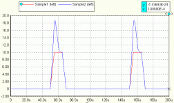
This is when you shorten the timing of one of the batteries pulses delivered to the capacitor.
 

Attachments

  • PWM Battery 003.gif
    PWM Battery 003.gif
    9.8 KB · Views: 1,518
Status
Not open for further replies.
Back
Top