A123 AMP20M1HD-A Battery pack kit

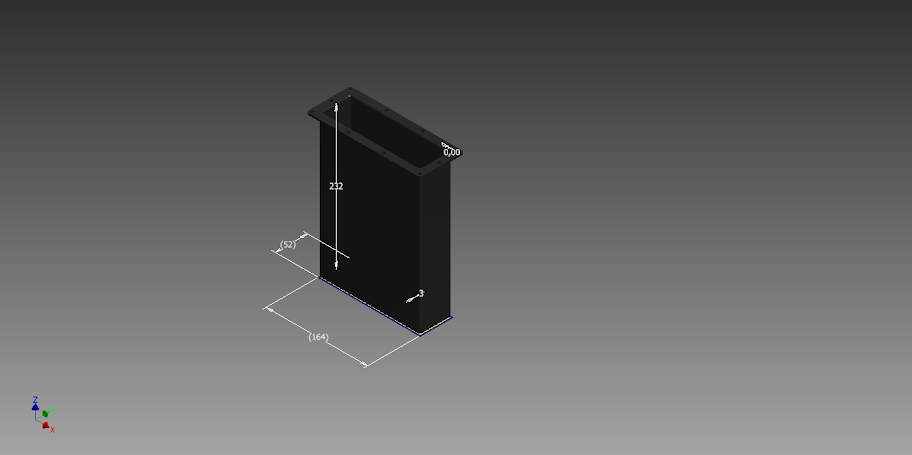
Agnius, check out this polycarbonate case that will fit your battery pack perfectly:
http://www.amazon.com/BUD-Industrie..._6?s=industrial&ie=UTF8&qid=1346993682&sr=1-6

31mSA6AaoCL._SL500_AA300_.jpg


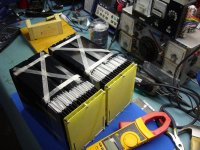
BTW, that 4S1P pack has worked perfectly in turning over what is a very high compression motor in my Porsche GT3. The starter motor actually spins the motor up faster than with my previous 25lb AGM battery and even though the alternator in the car only outputs at 14.0 volts, the cells have kept charged at 90%+ capacity.
 
Hi Steve. Thanks for the link. I think i will need those terminals you were talking about on Porsche forum. Combined with this box it will make one sexy battery. Cheers
 
agniusm said:
Hi Steve. Thanks for the link. I think i will need those terminals you were talking about on Porsche forum. Combined with this box it will make one sexy battery. Cheers
Hi. Thanks & bump what I nominate as the "sexiest battery" on the ES forum. By sexy, I'm assuming a highly charged relationship with the right chemistry. The Tulisa of batteries! Agniusm, I'm still in love with my battery. We had a little strain there in our relationship after two of her tits fell off. But we did the surgery and she's got all 12 tits putting out the juice and I've been sucking her dry every day since!
 
I have build myself vacuum forming machine. Will try to make battery case to sandwich bottom case my kit and top cover to form protected battery. I am thinking perhaps making 12S, 16S, 24S complete battery packs (-BMS) available to Europe. Just thinking stage at the moment as few vacuum formed samples did not came out right. i have to consult someone who is doing this type of work. I am thinking, i need right molds to get it up to selling quality.
Here is a thread on vacuum forming machine out of scraps:
http://endless-sphere.com/forums/viewtopic.php?f=2&t=47353
 
Tested soldered nuts on my kit and they do hold very good. This would further simplify assembly and eliminate short circ risk:
IMAG1108.jpg

I am trying to sort out enclosure for these kits to build up nicely into sealed battery pack. Would use 3mm polypropylene for cell enclosure and 2mm for top cover:
Bottom%2520part1.png

top%2520part1.png
 
Good one, how else could it be done, a cage nut through through the tab slots probably would get in the way on the top side.
 
agniusm said:
I am thinking perhaps making 12S, 16S, 24S complete battery packs (-BMS) available to Europe. Just thinking stage at the moment as few vacuum formed samples did not came out right. i have to consult someone who is doing this type of work. I am thinking, i need right molds to get it up to selling quality.
Here is a thread on vacuum forming machine out of scraps:
http://endless-sphere.com/forums/viewtopic.php?f=2&t=47353

I am interested of 12s/16s complete build. I am from Finland.
 
agniusm said:
Tested soldered nuts on my kit and they do hold very good. This would further simplify assembly and eliminate short circ risk:

An alternative would be to solder brass blocks with M4 tapped holes to the board, but they sure wouldn't be cheaper. Brass nuts on the back I assume?
 
Yes, I was thinking square brass nut, M3, soldered.

At the moment this looks expensive. something like 700 for 12s battery. This is due higher cost of matched and tested cells at 31USD.
 
Yes it could only be problems making a kit for someone or for sale with Victpower short tab cells. In a case like that I could only use new cells and the cost goes up.
 
Pcb blind rivet nuts.
Similar to OSNs but with yours, rivets from the back of pcb and pressed in semiflush with a special rivet attachment.
No soldering necessary, have to go into full scale production now :wink:
 
Semi flush makes clamping useless. This was thought over long ago. Another point is you have to make hole a lot bigger for the rivet which leaves almost none PCB left. Distance between tab slots = 6mm. holes are 3.5mm 3mm rivet probably be 4.5mm outside diameter which leaves 1.5mm to hold rest of PCB or .75mm per side, not so good :)
Got some pricing on the enclosure. Bottom sections needs to be welded, top section vacuum formed on negative mold. Molds are 70USD for 6S probably more for 12, 16, 24S. Complete pricing looking high.
Paul sells 12S for 590USD and my approach would bring me to 700USD.
 
Yeh your right no meat left that's why pcb, whilst it makes for neat, its another reason to not like for a power build.

Could tap 5 holes in a bar on flip side and countersunk 2x screw fix from the top.
A lot of ways to do it, some ideas you take on with no credit and others you just dis.
Good businessman.

Zip did Chinese A123 arm buy it out and Johnson Controls have control of USA A123.
Havnt seen the last of this tech can't suppress like Nimh, probably just pump up price, shot in the foot i think offering them for sub $20 price they were, be hard to sell at $40+ again to market.
 
Yesterday i finished testing each single A123 cells and began to assemble the kit.

Everything worked fine and i am 100% satisfied with the kit quality.
Except that i feel a bit confused about the "L" shape main contact made of copper and that make direct electrical contact to the aluminum tab of the cell.

There is an important galvanic corrosion potential between aluminum and copper. Maybe not in the next week, but over the years it will get worst and begin to oxidyze.

I am looking for a solution about that.

Doc
 
OK, i hear you. I am thinking now if you can use leftover copper, nickel plated tab from negative to squeeze in between positive aluminium tab and copper L shape terminal? Just punch the holes and it should protect from galvanic corrosion. Also you can tin the narrow edge of the L. I am not sure if it creates a lot of resistance. Hope that helps.
Would you post few pictures when you have done your pack?
Regards
 
agniusm said:
OK, i hear you. I am thinking now if you can use leftover copper, nickel plated tab from negative to squeeze in between positive aluminium tab and copper L shape terminal? Just punch the holes and it should protect from galvanic corrosion.
Would you post few pictures when you have done your pack?
Regards


I will post the pictures as well !

Both 16s will be added to my DsS 2011 Zero motorcycle just under the stock battery. They will fit perfect and that will give me 40 more Ah so the total Ah will be 100Ah.

14s LiMn fit perfect in parallel with 16s LifePo4.

I will also add my 320cells of model 26650 M1 2.3Ah from A123 wich would give me another 42 Usable Ah.
This zero 2011 will probably be the highest range 2011 ever made with about 150 real km range on highway and about 220km in the city!

The 16s A123 module will probably give about 50-100A average. All cells was tested and give me minimum of 18.5Ah at 100A (5C). cells from Victpower ( ful tab made in USA)

The average Ri of each cell is about 0.74 miliohm at 22 celsius 50% SOC wich is excellent!

Doc
 
I've been searching around but it seems hard to find a source for cells for this pack/kit. I am afraid to buy from OSN or victpower, is there a place or two that is reliable?
 
I've just done a 30km ride using 48v 20ahr a123 cells from elcheapo taobao vendour, resting voltage after ride of the cells is between 3.292 to 3.296v ( via cell logs)
anyone care to have a guess at how many ahr are left? I'm assuming resting voltage after a ride can give some indication of ahr capacity left.
 
agniusm said:
whatever said:
I'm assuming resting voltage after a ride can give some indication of ahr capacity left.

This assumption is wrong. Same mistake I was found.
Here's a graph made from 49 trips, Cellman 16S 5P A123 26650 pack. DOD percentage calculated by substracting CAs' spent WH from assumed pack capacity of 607,2 Wh. I'd say something can be predicted.

 
Resting voltage has nothing to do with voltage under load 3.2v may be 2.8v as soosn as you hit the throttle. So not as much meaning as we would hope. That's why I would only take my a123 20ah cells down to 3.2v.
 
Here is my battery built :wink:

I finally started using these great kit i bought from you Agniusm :mrgreen:

These are perfect!

[youtube]bvr-EoLs5pE[/youtube]


Doc
 

Attachments

  • P1090465_800x600.jpg
    P1090465_800x600.jpg
    103.2 KB · Views: 3,429
to gua rana
your volts/dod graph is very interesting, is the curve traced a line of best fit predicted by computer? is there a formula predicted also.
There is definitely a pattern there good enough to predict capacity remaining. It looks like a parabolic curve. Below 40% theres not much data
around that area so hard to say much there, but after 60% dod the data looks very predictable.
I've modified your graph by dividing by 16 to give cell voltages ( just so its a bit more useable), I note you have 6p pack.
This type of data for the 20ahr cells would be very useful if anyone has some.
I've included 50% dod on the graph at that point you at least know your going to get home on the bike.
I'm going to save my data and keep a record, though i'll just use distance travelled against voltage

volts dod 26650 a123.jpg
 
Back
Top