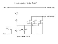
Active pre-charge/inrush control

So it sounds like the inrush to the caps is high enough to blow the one with the path of least resistance.
If the pack is suddenly connected to the caps in the controller (even with no motor) the inrush current will be very high, possibly like 1000 amps depending on the voltage and wiring resistance and cap ESR,

I think slowing down the turn on time will let the FETs act like precharge resistors enough to dramatically reduce the current spike. Try a bigger capacitor like at least 10uF. If it gets too big, it might not be fully on by the time you want to draw some real power. I think even at 100uF it would be up in a couple of seconds. You can measure the gate voltage as you switch on the gate drive and see how long it takes to get up to 2-3 volts. I think a 4310 will be amost fully on by 5v and about as on as it gets by 9V (data sheet would tell). You can do this with no load.

I think the left hand one prefers to blow first because it has the lowest wiring resistance. Feeding the negative wires from opposite sides would even this out, but that would only randomize which one blows first if they get too much current.
 
A simple but useful circuit. And I agree, these should be standard in controllers given how much zap you get at even modest voltages.

Any reason you couldn't use 2 of these circuits with a double pole switch to put 3 seperate batteries into series with the flick of a switch ?
I'm thinking it would be great for parallel charging without having the physically break any of the connections.
 
Hyena said:
A simple but useful circuit. And I agree, these should be standard in controllers given how much zap you get at even modest voltages.

Any reason you couldn't use 2 of these circuits with a double pole switch to put 3 seperate batteries into series with the flick of a switch ?
I'm thinking it would be great for parallel charging without having the physically break any of the connections.

The FETs have an intrinsic body diode that would still be there. I'll have to think about whether that would work.
For sure it would work if you used twice as many FETs and arranged them back to back so it was really off when you turned it off. The parallel connections would still have to be manual and it would be BAD if the switch turned on when they were still parallel. Some kind of safety interlock would be a good idea.

Below is my version of the circuit. This should be fine from 24v up to whatever the FETs are rated for. LVC input is optional for those that want an active cutoff. You could also leave the switch out and have it permanently on. Anytime the battery is disconnected, it will reset and turn off so there won't be a spark when you connect next time. You'd just have to make sure it stayed disconnected long enough to drain the cap fully.

Edit: Don't use this circuit. The FETs will fry. See later versions.

Inrush Limiter 2.jpg
 
Awesome thread guys I was just thinking its time to design a pre-charge circuit.
 
fechter said:
... LVC input is optional for those that want an active cutoff...
do you think of the celllogs to do this? but then you need to modifiy them so current draw over all cells is equal. and i'm not sure if it's safe to have them connected all the time - even with power management enabled.
 
Arlo1 said:
Awesome thread guys I was just thinking its time to design a pre-charge circuit.

I looked at this for quite a while. Ideally you'd want a constant current of something like 1A to precharge the controller caps, then engage the main switch once it comes up. This would allow for a safety in the event of a controller short. Unfortunately it becomes quite complicated if you have a separate precharge circuit with fail-safe features. The circuit posted above is simple enough to make it somewhat practical.

izeman said:
do you think of the celllogs to do this? but then you need to modifiy them so current draw over all cells is equal. and i'm not sure if it's safe to have them connected all the time - even with power management enabled.

A CellLog or isolated CellLogs could trigger this, but as you point out leaving CellLogs connected all the time is going to result in unbalancing the pack. If the CellLogs were only attached when you were riding, it might be managable. I was thinking more like Methods' HVC/LVC boards, but it should be possible to interface other types of BMS circuits. Personally, I'm not a big fan of active cutoffs. Interrupting a 1kW+ load is asking for smoke. It is more useful is for low load conditions like forgetting to turn the controller off for a week.
 
fechter said:
Arlo1 said:
Awesome thread guys I was just thinking its time to design a pre-charge circuit.

I looked at this for quite a while. Ideally you'd want a constant current of something like 1A to precharge the controller caps, then engage the main switch once it comes up. This would allow for a safety in the event of a controller short. Unfortunately it becomes quite complicated if you have a separate precharge circuit with fail-safe features. The circuit posted above is simple enough to make it somewhat practical.
I think my plan is to use a precharge with a contacter.
You put a big fuse on the contacter and a smaller fuse on the precharge and if you get the precharge fuse just right it will pop if there is a short and the caps dont charge hi enough.

I was thinking a voltage divider off the output side of the precharge to a transistor to the switch wire for the contactor. SO you just flip a switch and the precharge starts then the caps get hi enough and the contact turns on. Then Maybe have a yellow and green led on the dash so when I turn the bike on it will tell me the stage and if it just stays yellow I will know there is something wrong.
 
That sounds similar to what I was working on. You start precharge and monitor the voltage then switch on the main contactor when it reaches close to 100%. One issue is a lot of controllers are set up to be always on and will draw 50ma or so. This might limit the amount of precharge you can get through a resistor. When the load gets within about 12v of the pack voltage, I think you could switch on the contactor safely.

I thought of using a big resistor that was thermally attached to a PTC for the precharge. Normally it would come up in a couple of seconds, but if it was shorted, the resistor would overheat and trigger open the PTC to keep the temperature below 100C.

It just seemed to get too complicated to make it all bullet proof and reliable. I like the simplistic approach.
 
OK I am having problem with this circuit. I am getting the symptom of izeman.

First Connection works fine, but then it would not turn off. i.e. something have screwed up the FETs.

I did not try to reconnect as I know it will spark.

Any ideas? I have wasted quite a bit of FETs/board so far testing the damn circuit.

One thing I do notice is everything starts up instantly. So I am suspecting startup is too fast?

I am using 47K and 10K and 1uF Cap. And using 4110 FETs.

I am down to my last few FETs.

izeman, did you try the bigger cap? Fetcher is using 10uF instead of the what Jeremy recommended of 1uF. If so, does it help?

I just did some calculations, using 47K and 1uF, the charging will happen in 0.047 sec (RC timing). This mean it fully charges in roughly 1/20 of a sec. Using 10uF, this will become roughtly 1/2 sec. I think this is where our problem is. 1uF is too small.
 
Hyena said:
A simple but useful circuit. And I agree, these should be standard in controllers given how much zap you get at even modest voltages.

Any reason you couldn't use 2 of these circuits with a double pole switch to put 3 seperate batteries into series with the flick of a switch ?
I'm thinking it would be great for parallel charging without having the physically break any of the connections.

I was thinking about this one, but I think it would be too risky even if you put one front facing with another. Again it has to do with the intrinsic diode. You maybe able to disconnect the connection, but once you plug in the battery to the charger with common ground, PUFF. If you have one facing opposite direction and possibly single switch, then maybe... But I would have to do the analysis.
 
mvly said:
izeman, did you try the bigger cap? Fetcher is using 10uF instead of the what Jeremy recommended of 1uF. If so, does it help?
i tried a 10uF now. no problem so far. i'd even use a 47uF to be on the safe side. i found the same circuit on a german board some time ago and they use a 47uF.
 
Also keep in mind that the FETs do all their 'turning on' over a small voltage range, from about 2v to 5v. I think we want this range to take about 1 second to pass through ideally.
 
fechter said:
Also keep in mind that the FETs do all their 'turning on' over a small voltage range, from about 2v to 5v. I think we want this range to take about 1 second to pass through ideally.
but there haven't been any problems reported by those ppl who built the circuit with 1uF.
maybe they have lower volt setups. i guess the higher the voltage, and the bigger the caps, the higher is the pressure on the fets.
 
Right, higher voltage and bigger caps will stress the FETs more. Wiring resistance is a big factor too. Long wires from the battery to controller will reduce the peak current.
 
fechter said:
Also keep in mind that the FETs do all their 'turning on' over a small voltage range, from about 2v to 5v. I think we want this range to take about 1 second to pass through ideally.

One more simple question. Since the VDS of the FETs are really low, I.e. 0V, would it be possible to use cheaper less resistance FETs as oppose to the more expensive 4110 or 4115 for high voltage setup?
 
mvly said:
fechter said:
Also keep in mind that the FETs do all their 'turning on' over a small voltage range, from about 2v to 5v. I think we want this range to take about 1 second to pass through ideally.

One more simple question. Since the VDS of the FETs are really low, I.e. 0V, would it be possible to use cheaper less resistance FETs as oppose to the more expensive 4110 or 4115 for high voltage setup?

The FETs have to take the full pack voltage initially, so need to be rated for it. If you run a lower pack voltage, then yes, you should use a part with the lowest possible on resistance.
 
OK just tested with 10uF and 20uF. Same result. I am starting to think I need a zener...

Izeman did you run a zener on yours?
 
mvly said:
OK just tested with 10uF and 20uF. Same result. I am starting to think I need a zener...
Izeman did you run a zener on yours?
no. i don't see the need for a zener. tough it's just a kind of insurance. i safe you in case you calculate the value of the resistors wrong. but i calculated them, and on-gate voltage is exactly as calculated.
i don't know how this voltage could be higher than what you calculated. i would not expect much from it. but it can't make things worse - so if i got time to buy one, i'll do so.
maybe you got a bad batch of fets?
 
mvly said:
OK just tested with 10uF and 20uF. Same result. I am starting to think I need a zener...


What resistors are you using? I think something in the 1M range will slow it down enough.
If you look at my schematic, the zener is mainly there to allow a wide range of voltage without needing to change the resistor values. As long as the gate never sees over 20V, it shouldn't blow up the gate. The zener would also protect against transient spikes that could be generated by inductance in the wiring.
 
fechter said:
mvly said:
OK just tested with 10uF and 20uF. Same result. I am starting to think I need a zener...


What resistors are you using? I think something in the 1M range will slow it down enough.
If you look at my schematic, the zener is mainly there to allow a wide range of voltage without needing to change the resistor values. As long as the gate never sees over 20V, it shouldn't blow up the gate. The zener would also protect against transient spikes that could be generated by inductance in the wiring.

I am using 47K. Just blew a few more FETs.

OK here are my specs:
47K on the top. 10K on the bottom. Zener diode 12V on the bottom just to be safe. And 20uF ceramic caps.

Still blew.

Keep in mind it only have 1 FET on the board to save on the board and FETs and possible reuse part of the boards.

I am just about to give up on this circuit idea. Just wasted $150 on all the materials and nothing to show for it other than blown FETs and boards that do not work.
 
Bummer, but you are providing some valuable feedback for design input. Your particular setup (voltage and controller) must be close to a worst case for this design.

A single FET makes it harder since it has to handle all the current, but if we make it go slow enough that a single survives, it should be very robust with several in parallel. This is certainly possible.

It sounds way too fast still. 1M top and bottom with 12V zener and 20uF seems like it should be in the ballpark, but it would be good to do an actual measurement of the switching speed. What we want is the FET to go from off to almost fully on in about 1-2 seconds. If I get time I could try to set up a test circuit and measure with a scope, but only have an analog scope that has a hard time measuring single events. A digital storage scope would be much better.

It might make sense to build it 'too slow' to start with. At least you won't be blowing up expensive parts. 1M and 100uF? If it's too slow, there's a chance it won't be fully on before you hit the throttle on the controller. If the controller has a working LVC, this won't cause destruction, but could be annoying. If the controller doesn't have a LVC, then there's a chance for some smoke if the FETs are half way on.

Maybe some guys good with spice (or good old fasioned math) can tell me if I have a 50v source feeding a 100uF cap through a 500k resistor, how long does it take to go from 2v to 4v?
 
fechter said:
Bummer, but you are providing some valuable feedback for design input. Your particular setup (voltage and controller) must be close to a worst case for this design.

A single FET makes it harder since it has to handle all the current, but if we make it go slow enough that a single survives, it should be very robust with several in parallel. This is certainly possible.

It sounds way too fast still. 1M top and bottom with 12V zener and 20uF seems like it should be in the ballpark, but it would be good to do an actual measurement of the switching speed. What we want is the FET to go from off to almost fully on in about 1-2 seconds. If I get time I could try to set up a test circuit and measure with a scope, but only have an analog scope that has a hard time measuring single events. A digital storage scope would be much better.

It might make sense to build it 'too slow' to start with. At least you won't be blowing up expensive parts. 1M and 100uF? If it's too slow, there's a chance it won't be fully on before you hit the throttle on the controller. If the controller has a working LVC, this won't cause destruction, but could be annoying. If the controller doesn't have a LVC, then there's a chance for some smoke if the FETs are half way on.

Maybe some guys good with spice (or good old fasioned math) can tell me if I have a 50v source feeding a 100uF cap through a 500k resistor, how long does it take to go from 2v to 4v?

The other factor I might be doing wrong is using Surface mount Cap. Ideally it shouldn't matter, but it seems like your guys are using electrolytic caps. I'm going to try that later today if I get a chance. The resistors are also surface mounts, but that should not matter.
 
Surface mount shouldn't make any difference as long as the values are right. Electrolytics are generally much cheaper than MLCCs but either should work.

I still didn't have time to test a circuit.
 
I have an idea for a design variation. If we use a capacitor to provide some negative feedback from the drain to the gate, we can make the output ramp up at a nearly constant rate. This would take a lot of guesswork out of the charging speed and really keep the peak current on the FETs way below their ratings. I'll post a schematic when I get a chance. Downside is a couple more parts maybe.
 
Back
Top