Active pre-charge/inrush control

fechter said:
2.5mm2 wire should be OK, but a little small. As long as they are short, there won't be much loss.

The reason for the ground connection on the switch is to speed up the turn-off. It will work without it, but when you turn the switch off, it might take 30 seconds before it really turns off. This might be OK in most cases. It might be bad in an emergency, like stuck throttle. It would also be bad if there was a heavy load (motor running) when you turn it off.

thanks. voltage drop should be minimal. and i can live with that.
i thought that switching to ground would speed up shut down, but wasn't sure. reasonable if you need it as kill switch. my switch will not be near my handlebars, so in case there is an emergency i won't be able to reach it anyway :(
i tried with a single fet, and it seems there is no real ramp up. my voltmeter needs some tenth of a second to show voltage, but it's definetly not 2s until full voltage goes through.
 
If you have another kill switch, then slow turn off should be fine.

If you are measuring without the controller attached, it will look fast I think.
In your setup, charge time would be around 1 second. This should be OK, but just for experimentation, you could increase the 1M resistor or increase the capacitance to slow it down even more. If you add another 1M in series to the existing one, it should double the time.

I looked at the output and gate voltages with a scope when I was testing. The gate is interesting, it goes quickly to the gate threshold voltage (around 2-3v depending on FETs) and holds steady there for the duration of charging, then goes up to the 12v zener threshold.
 
fechter said:
If you have another kill switch, then slow turn off should be fine.

If you are measuring without the controller attached, it will look fast I think.
In your setup, charge time would be around 1 second. This should be OK, but just for experimentation, you could increase the 1M resistor or increase the capacitance to slow it down even more. If you add another 1M in series to the existing one, it should double the time.

I looked at the output and gate voltages with a scope when I was testing. The gate is interesting, it goes quickly to the gate threshold voltage (around 2-3v depending on FETs) and holds steady there for the duration of charging, then goes up to the 12v zener threshold.
I measured with controller connected. But I will check gate voltage as well. I also will test with 2 resistors.
 
i must be doing something wrong. as soon as i connect this to my battery, there is zero ohm between drain and source.
after some time this goes away.
how can this happen when there is no voltage connected to gate?

this is how i connected everything. maybe someone is so kind to check it:

Circuit.jpg
 
Ah, yes, the gate has nothing to pull it down. If not using the ground connection on the switch, you need another 1M resistor from gate to source (across the zener) to turn the gate off.
 
fechter said:
I looked at the output and gate voltages with a scope when I was testing. The gate is interesting, it goes quickly to the gate threshold voltage (around 2-3v depending on FETs) and holds steady there for the duration of charging, then goes up to the 12v zener threshold.
i added a 2 way switch. removed the 1m resistor between gate and drain again. now when closing the switch, gate voltage goes to 2.5v, and stays there. the controller doesn't seem to be charged. output voltage stays low also.
what's wrong? i used all resistors and cap as suggestested in v3.

Edit: sorry forget my last post. It does work. I connected the battery with crocodile clamps and thin cables to act as a fuse in case something goes wrong (what happened several times and 1.5kwH of charge and 80V is nothing to play with). Those thin cables seem to have caused troubles. I directly connected everything with 10awg wire and it worked.
One more question: with the switch in the off position (bridging GND to gate) it still takes some seconds for the controller voltage to come down. Why is that? To me this seems to be the charged caps in the controller. Correct?
 
Correct. Even if you unplugged the battery, the voltage would come down slowly due to the stored charge in the capacitors.
 
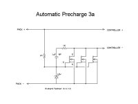
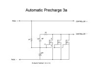
If you don't want to use a switch, you can use the schematic below. This will be 'always on'. Disconnect the pack to turn off. Anytime the pack is connected, it will automatically precharge and turn on. This arrangement will require a minimum pack voltage of around 14v.Automatic Precharge 3a-schematic.jpg
 
fechter said:
If you don't want to use a switch, you can use the schematic below. This will be 'always on'. Disconnect the pack to turn off. Anytime the pack is connected, it will automatically precharge and turn on. This arrangement will require a minimum pack voltage of around 24v.

This is very interesting, thanks. You wouldn't happen to have one for sale? Failing that what Wattage resistors etc. should I use to build one? thanks
 
No product for sale (yet).
All the resistors can be very tiny. The zener diode should be 1W (but 1/2W would problaby be enough).
None of the values are critical, just the capacitor needs to be non-polar and rated for full pack voltage.

In thinking more about it, the lower 1M resistor in the last schematic is probably unnecessary if you don't have a switch. When the pack gets unplugged, the controller will drain everything down in a few seconds.
 
Thanks. I'll give it a few weeks for your thoughts to get finalised (in case you come up with design changes) then see if you've decided to sell, otherwise I'll make one up. It's a nice idea as an improvement on a switch- I can't forget to use it, and it should be less susceptible to damage through bumping it.
 
I made the first version of this circuit, and it worked fine...
until I plugged in my DC/DC converter which turned the whole thing off.
Now the gate voltage is always zero. The resistor seems fine, and so does everything else. What could the DC/DC converter have done to break the thing?
I was getting 53V across source and drain, even when the switch from battery+ to 33k resistor to gate is off, and that does not seem like a normal value at all. Turns out my turnigy wattmeter was continuous from + to - and energized the drain side of circuit.
I am not getting any voltage at the gate with the switch on.
Did I blow the IRFB 4110s? Or what the hell happened?
My pack voltage is 48V nominal, 60 max, and I am using a 33k gate resistor.
Thanks for your help!
 
You made the circuit on page 1?
If so, try disconnecting all power and measure resistance from gate to source. If near zero, try disconnecting the cap and measure again. It should be 10k.
 
No resistance as in a short or open?

If shorted, it means one or more FETs is blown, keeping the voltage zero.
If it measures open, I would next check the 33K resistor. I would be likely open (though that would be a very unlikely failure).

If the FETs are shorted, you can try separating the gates and measure them one by one. You might be lucky and have only one that actually failed.
 
fechter said:
No resistance as in a short or open?

If shorted, it means one or more FETs is blown, keeping the voltage zero.
If it measures open, I would next check the 33K resistor. I would be likely open (though that would be a very unlikely failure).

If the FETs are shorted, you can try separating the gates and measure them one by one. You might be lucky and have only one that actually failed.

I think gate to source is shorted. 33k resistor is OK.
I read in the thread that several other members have had trouble with the design on page 1 ( many many blown FETs!)
I only have components for the page one build- is it worth the trouble to get the additional components for the new design?

Thanks a bunch~
 
potatorage said:
I read in the thread that several other members have had trouble with the design on page 1 ( many many blown FETs!)
I only have components for the page one build- is it worth the trouble to get the additional components for the new design?

Thanks a bunch~

I think so. The additional parts are generally quite inexpensive and can often be harvested from old dead power supplies. The linear ramp circuit will keep the FETs well within their safe operating area during precharge. The zener diode allows operation over a very wide voltage range, so no need to change parts when changing voltage. The linear ramp circuit will also allow full precharge even with a small DC-DC coverter on the load side.
 
fechter said:
Arlo1 said:
I think you could make a few mild changes to this to turn a contacter on.

OK, here you go!

This arrangement has the contactor on the negative side so we can use N channel FETs. The FETs don't need to be super high current, but it wouldn't hurt. It would be possible to use P-channel FETs and design the circuit to switch on the positive side, but I don't see any real advantage to this.

If the contactor coil is rated for the pack voltage, it can look like the drawing. In most cases, the contactor coil is rated for a lower voltage, so either a big resistor in series with the coil or a DC-DC converter can be used between the circuit and the coil. The main DC-DC coverter for a vehicle could be driven off Q2. If using a DC-DC, make sure Q2 is rated for the current it takes. Both Q1 and Q2 should have some kind of heat sink, but they should only need it during the two seconds during precharge.

Q1 does the precharging. Once the controller gets up to full pack voltage, the dV/dt drops to zero and allows Q2 to turn on. One advantage of this arrangement over the typical resistor precharge is any additional drain from the controller circuitry or a DC-DC converter won't prevent it from reaching full voltage.

If the controller is shorted, the fuse will blow, preventing the contactor from kicking in. The fuse should be around 2A plus whatever the DC-DC or coil takes.

In practice, turning on the switch starts precharge, which will take about 2 seconds. After that, the contactor automatically engages.
Do I just need to calculate the resistor for the contactor from the resistanc of the coil when energized and concider it a voltage divider?
 
Arlo1 said:
[
Do I just need to calculate the resistor for the contactor from the resistanc of the coil when energized and concider it a voltage divider?

That should work. The dropping resistor will probably need to be high wattage.
The other way is to calculate the coil current and use that to calculate the resistor based on the voltage drop needed.

It takes more current to pull the contactor closed than it does to hold it. If you want to get fancy, you can use two resistors in parallel, and use a big capacitor in series with one of them to give a boost at first.

It is a good idea to have a reverse biased diode across the coil to prevent a high voltage spike when it turns off.
 
OK, to recap:
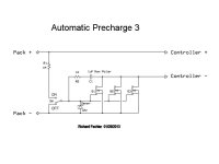
Two versions of the circuit, one with a switch and one that's 'always on'. With either version, the battery can be disconnected and reconnected without a big spark regardless of switch position. In the switch version, the drain on the pack is ZERO when the switch is off. In the 'always on' version, it is assumed the pack gets disconnected to turn it off. During precharge, the voltage applied to the load (controller) is a linear ramp, which keeps the cap charging current constant and keeps the FETs from blowing up. The FETs are acting as both precharge resistor and switch. No wasted silicon.

The pack + line going to the switch is fed by a 1M resistor. If you short out the wires or touch them, nothing bad happens. Worst thing that can happen is turning off the load when you don't want to. The switch can be on the circuit board or mounted remotely by thin wires.

For up to 72v nominal, a 1uF cap should be enough. Precharging will be done in about 1 second. For higher voltages, a larger capacitor may be a good idea to keep the precharge current low. Capacitor needs to be non-polar and rated for full hot-off-the-charger voltage (plus a little head room).

FET choice depends on system voltage and maximum sustained current. IRFB4110s are good up to 100v and I roughly estimate 20 amps per FET to keep heating reasonable. If you run 100A peak, I suggest 5 parallel FETs. For 40A controllers, 2 FETs should be enough.

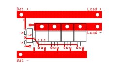
I included a couple of sample layouts. I would make the rectangular bus bars out of flattened soft copper tubing (readily available) and drill and bolt the FET tabs. The positive line could just be a section of heavy wire with a tap to the circuit made with a small wire. This circuit could be easily built on a piece of perf-board using wire for the traces. I'm showing 4 FETs, but any number can be used depending on the current requirements. I envision placing the board in heat shrink or a small enclosure with pigtail wires coming out to connectors and more or less permanently attached to the controller side.

Automatic Precharge 3 schematic.jpg
View attachment 2
Automatic Precharge 3a-schematic.jpg
Automatic Precharge 3a layout.jpg
 
alsmith said:
Any decision on if selling as built units or kits?

I won't be able to offer these myself, but I'm more than willing to work with someone who wants to make and sell them. I did something like this with my Mini Meanwell limiter boards. One nice aspect of doing a kit is you can choose the FETs to match your application. The switched version could easily be made always on by placing a jumper where the swtich goes.
 
fechter said:
alsmith said:
Any decision on if selling as built units or kits?

I won't be able to offer these myself, but I'm more than willing to work with someone who wants to make and sell them. I did something like this with my Mini Meanwell limiter boards. One nice aspect of doing a kit is you can choose the FETs to match your application. The switched version could easily be made always on by placing a jumper where the swtich goes.
If you guys want I can make them and sell them. It would be a thing where there done without much profit just because its fetchers idea. I would be willing to do this because Im goign to use a precharge setup for my controller im working on.
 
You could possibly get icecube57 to make 'em. I might even be interested too. There are options.
 
i think about another layout modification. taking one big copper bar 30x45x6 mm for 4 fets. fets are on one side, facing at each other with their pins in groups of two. drain is the same as the copper. in the bar there are two 12mm slots on the top side and below. these will fit a (from the drain isolated) 10mm copper bar for source on the upper side, and gate on the down side. holes drilled for connecting the gates to the backside.

IMG-20130321-00166.jpg


i hope you can get the picture ;) it's hard to explain, but i should be able to post a picture of it on the weekend.
 
Back
Top