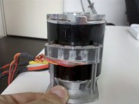
Adding hall sensors to outrunners

I'm itching to get into this game too, but the turnigy hxt 80-100 is on backorder and I am getting impatient. Does anyone have the slightest idea of how long I might have to wait?

Or, does anyone have one of these they're not using, that I can buy? :twisted:

I intend on copying gwhy's setup for the halls. I've asked him about getting one of those PCBs that makes mounting so convenient. I am also considering an adaptive sliding mode fuzzy-neural controller to adjust the position of the halls in real-time.
 
dozentrio said:
I'm itching to get into this game too, but the turnigy hxt 80-100 is on backorder and I am getting impatient. Does anyone have the slightest idea of how long I might have to wait?

Or, does anyone have one of these they're not using, that I can buy? :twisted:

You can always go direct if you don't mind paying more and a bank deposit to china.
 
dozentrio wrote:
...I am also considering an adaptive sliding mode fuzzy-neural controller to adjust the position of the halls in real-time.

I am intrigued. Please tell us more :shock:
 
Hi all, Im new to this forum and boy am I glad I found you guys.
I am working on a project which requires me to have a smooth start up using a brushless motor with alot of load at starting.
I already have been using a turnigy Motor with a brushless controller but the cogging is too bad.
I have not purchased a sensored controller and have tried getting the timing right on the halls, but it seems impossible,
In one position it just makes noise and goes nowhere (0% I think) then slightly moving it advance or retard it judders between phases.
I am using 3 halls externally mounted at 17.1 degrees and have tried in various position over a 30 degree range.
I hope to see some of your results under load to prove this can be done.
Thanks.
 
Burtie said:
dozentrio wrote:
...I am also considering an adaptive sliding mode fuzzy-neural controller to adjust the position of the halls in real-time.
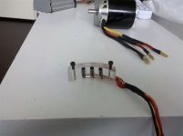
I am intrigued. Please tell us more :shock:

I'm sorry, I said that part in jest. :p Whenever someone has absolutely no clue what they are doing in my field, they throw around these catch-words. Especially popular, is trying to use neural networks to solve all problems.

I think adjusting the timing would be sufficient for any issue related to hall position. I wonder if it's possible to adjust the timing of EACH hall signal individually, though. At very small intervals too? Say, tenths of a degree? That way, even if you haven't mounted them exactly perfectly, the software could adjust the signal so that it runs perfectly smooth. I could potentially contribute on the code for that.
 
I said that part in jest.
Cool, that one went right over my head! :mrgreen: :mrgreen:


dozentrio wrote:
I think adjusting the timing would be sufficient for any issue related to hall position. I wonder if it's possible to adjust the timing of EACH hall signal individually, though. At very small intervals too? Say, tenths of a degree? That way, even if you haven't mounted them exactly perfectly, the software could adjust the signal so that it runs perfectly smooth. I could potentially contribute on the code for that.

A very interesting point. -See reply inTiming Adjuster Tool thread, here:
http://endless-sphere.com/forums/viewtopic.php?f=2&t=19054&p=278598#p278598
 
Cr3am wrote:
have tried getting the timing right on the halls, but it seems impossible,
In one position it just makes noise and goes nowhere (0% I think) then slightly moving it advance or retard it judders between phases.

Hi Cr3am, welcome to ES.

Assuming you have the sensors at 17.1 deg intervals and all the same way up, sounds like your problem might be one of:

a) One of the sensors not functioning, or not connected to the controller reliably
or b) Wrong hall wiring sequence
or c) Controller set for 60 degree mode (without middle sensor flipped upside down)

Let us know how you get on.
 
Burtie said:
Cr3am wrote:
have tried getting the timing right on the halls, but it seems impossible,
In one position it just makes noise and goes nowhere (0% I think) then slightly moving it advance or retard it judders between phases.

Hi Cr3am, welcome to ES.

Assuming you have the sensors at 17.1 deg intervals and all the same way up, sounds like your problem might be one of:

a) One of the sensors not functioning, or not connected to the controller reliably
or b) Wrong hall wiring sequence
or c) Controller set for 60 degree mode (without middle sensor flipped upside down)

Let us know how you get on.
Hey thanks. I am off to RS Tomorrow and getting some SS411A's as described here.
I have a feeling the microscopic halls that I have may have been damaged when soldering. :( Let see if it helps.
As I understand it I need to have the halls in the correct sequence, in the correct orientation and at 17.1 which simulates 120 degrees. I will also mount the halls about half way along the bell housing which I have seen has the biggest flux pattern. OK I only have the 1900w turnigy motor but it is the same theory of 12 stators 14 magnets.
I will keep you posted.
Thanks for the help. :)
 
Burtie wrote:
KiM
Dont be afraid of fitting hall sensors to your motor. If you dont mind just glueing them in the stator slots, which works well on my Stinky, it would be a very easy job for you to do (considering some of the amazing stuff I have seen you produce in the past )

You usually need to take these Turigy motors apart to fix the bearings anyway!

Go for it.
Burtie


Yes, you, based on my experience with one Turnigy 6374, can even run them edgewise. I was surprised when I noticed that the Hall sensor would work pretty much regardless of where I passed a magnet over them when I was playing with Fechter's Hall tester. So, I thought what the heck and they worked.

Update:

Well, they kinda worked. They worked on the bench but not under load. The motor would rev a bit and then stop; rev a bit then stop.

I milled some slots (same spacing, sequence, and locations), epoxyed the halls in, and the motor ran fine with lots of power..... but in the oposite direction!?!? That didn't matter much because my friction drive mount will work with the motor on either side.

So long story short, glue them in but facing up.

Larry Barefield
 
Hey guys, just to let you know of my progress.
I made a plastic ring that goes around the motor and fits perfectly, its made from a soffit vent ring from B&Q.
Anyway, I purchased 3 SS411A sensors from RS, £1.30 each and wired them + - 0.
We mounted the sensors at 120 degrees around the ring and placed it over the motor about half way.
Without timing it we tried it anyway to see what would happen and it worked PERFECTLY, even under extreme load! wow.
All my problems have been solved!
I will be tiding up the installation and seeing if timing it improves it at all.
I would like to thank all you guys for your help, problem solved in a matter of days!
I will be posting pics/video soon.
Thanks.
Cr3am.
 
hi,

i also added some hall sensors to my turnigy 6374 brushless motor.. and i am very pleased with it. much smoother than with a sensorless controller.

it is cnc'ed from some clear acrylic i had laying around.

foto1.jpg
View attachment 1
foto3.jpg
 
nieles said:
hi,

i also added some hall sensors to my turnigy 6374 brushless motor.. and i am very pleased with it. much smoother than with a sensorless controller.

it is cnc'ed from some clear acrylic i had laying around.

Now that looks very nice. cool
 
gwhy, Thanks!

the idea is there.. i need to put some time in the idea to ajust the timing..

right now i can change the timing by rotating the whole alu plate, but this can not be done when the motor is mounted.

if there is any interest i will look into making a few more of the acrilic parts.
 
Hey guys,

If I use winding sequence AabBCcaABbcC for a 12 teeth/14 pole motor and I want to place the hall sensors with 120 mechanical degrees on the inside of the motor, does it matter where each Hall sensor should be placed? Can I for instance use this sequence: A H1 a b B C H2 c a A B H3 b c C ? Or is it dependent on the controller type? Is it trial and error then or is there a quick way to determine the right place?

Cheers!
 
Fabbe said:
Hey guys,

If I use winding sequence AabBCcaABbcC for a 12 teeth/14 pole motor and I want to place the hall sensors with 120 mechanical degrees on the inside of the motor, does it matter where each Hall sensor should be placed? Can I for instance use this sequence: A H1 a b B C H2 c a A B H3 b c C ? Or is it dependent on the controller type? Is it trial and error then or is there a quick way to determine the right place?

Cheers!

Hi Fabbe,
If you space your sensors 120 degrees in the slots ( hall 1 in any slot, miss 3, hall 2, miss 3, hall 3 ) this will give you 120degree spacing and then its trial and error to find the sequence, but it isnt really that bad to work out, keep phase wires in one position and change hall sequence until the motor runs well, if the motor is running the wrong direction then swap phase wires until it runs the opposite direction. When testing for the correct sequence very high currents can flow if not correct so only tickle the throt to test.
 
Hi Guys,

I would also like to Add Hall sensors to my AXI 5325/18 ( http://www.modelmotors.cz/index.php?page=61&product=5325&serie=18&line=GOLD )
Nieles, I see that you mounted 3 Hall sensors spaced at about 1 centimeter from each other (which is not 120 degrees between each sensor).
What does it mean when saying you mount the sensors at 120 or 60 degrees? Is it 120 degrees between each sensor? When 60 degrees, should 6 Hall sensors be mounted spaced at 60 degrees ?
How far from the can should the sensors be mounted? is there an ideal distance from the can?

Any answers or additional images would be greatly appreciated !

Thanks
 
odedelen said:
Hi Guys,

I would also like to Add Hall sensors to my AXI 5325/18 ( http://www.modelmotors.cz/index.php?page=61&product=5325&serie=18&line=GOLD )
Nieles, I see that you mounted 3 Hall sensors spaced at about 1 centimeter from each other (which is not 120 degrees between each sensor).
What does it mean when saying you mount the sensors at 120 or 60 degrees? Is it 120 degrees between each sensor? When 60 degrees, should 6 Hall sensors be mounted spaced at 60 degrees ?
How far from the can should the sensors be mounted? is there an ideal distance from the can?

Any answers or additional images would be greatly appreciated !

Thanks

Assuming the this motor has 14 magnets, the spacing on the outside of the motor is 17.14 degrees between sensors ( this mimics 120 degrees spacing for the controller benefit ). My sensors are around 2-3mm away from the can . Hope this helps.
 
Will this setup work with any hub motor controller? Just curious if controllers like Lyen's controller will work with these??

By the way I just read through all this stuff and I feel like I at least have a basic understanding of how it works, so THANKS! I think I might be able to do this after all! LOL! I am considering ordering my first motor to play with soon!


ONE MORE QUESTION. How are you finding this, 17.1* spacing? Are you putting a degree wheel on the motor or something? Is there a tool I need?
 
Hello!

Can someone say me, how I know the distance between 2 of the hall sensors for my motor ( Turnigy C8085 170kv )

Thanks

ATB,
Manuel
 
i made this drawing for a forum memeber, so i will post it here also.

mani9876 said:
Hello!

Can someone say me, how I know the distance between 2 of the hall sensors for my motor ( Turnigy C8085 170kv )

Thanks

ATB,
Manuel

the distance between 2 sensors is 17.14 degrees with my setup (posted earlier)
 

Attachments

  • drawing.PDF
    25.2 KB · Views: 533
Whiplash said:
Will this setup work with any hub motor controller? Just curious if controllers like Lyen's controller will work with these??

By the way I just read through all this stuff and I feel like I at least have a basic understanding of how it works, so THANKS! I think I might be able to do this after all! LOL! I am considering ordering my first motor to play with soon!


ONE MORE QUESTION. How are you finding this, 17.1* spacing? Are you putting a degree wheel on the motor or something? Is there a tool I need?

Lyens controllers are just ordinary Infineon controllers, like those sold by Keywin, so the answer is yes, they will work. I've run several different types of outrunner from Infineon controllers, using home brew Hall sensors fitted to the motor.

If you don't want to figure out the 17.1 deg spacing, just go with three Halls spaced at 120 degrees, they will work fine with any 12 slot, 14 magnet outrunner.

Jeremy
 
nieles said:
i made this drawing for a forum memeber, so i will post it here also.

mani9876 said:
Hello!

Can someone say me, how I know the distance between 2 of the hall sensors for my motor ( Turnigy C8085 170kv )

Thanks

ATB,
Manuel

the distance between 2 sensors is 17.14 degrees with my setup (posted earlier)

And heres another drawing of the spacing i posted in another thread for 80mm cans and 64mm cans. Spose it makes more sense to be posted in this thread :D
View attachment 17.14deg.cad.pdf
 
Jeremy - gwhy,

Is there some advantage with specific models of motors for different hall spacing, as in better performance, lower no load current, etc?

Just wondering if KISS still applies and putting sensors @ 120 degrees around the casing doesn't make more sense?

Sorry for being ignorant, I've actually modded a few outrunners now but I just counted off the slots and guesstimated 120 degree placement then tuned for lowest no load current....

Thanks in advance!

-Mike
 
OK guys, I guess I didn't make the question clear, how do I actually determine the degrees on the motor? Do you use a degree wheel mounted on the shaft, or do you just use a protractor and more or less guess at the correct alignment? It can be quite hard to figure degrees on a round object without a degree wheel or something...
 
Back
Top