Adding hall sensors to outrunners

Your correct.

My timing is definitely out by a few °. I know this because the motor goes faster 1 way as opposed to the other.
Also, a quick look at the phase curves on the DSO proves my timing is slightly off.

However, this is no issue at all. I can very easily adjust the timing in the ESC software.
Im currently implementing a timing advance feature into the ESC, so when we reach 100% duty cycle, the ESC will advance the timing and we can go even faster :D.
 
ub3r said:
Your correct.

My timing is definitely out by a few °. I know this because the motor goes faster 1 way as opposed to the other.
Also, a quick look at the phase curves on the DSO proves my timing is slightly off.

However, this is no issue at all. I can very easily adjust the timing in the ESC software.
Im currently implementing a timing advance feature into the ESC, so when we reach 100% duty cycle, the ESC will advance the timing and we can go even faster :D.


OMG! Finally! ESC programable timing advance and sensor position correction! OMG! OMG! We've needed this so badly for so long!

You are a hero!
 
Im glad you like it.
I have another video ill upload shortly onto youtube. Shows the ESC in detail.
 
Video of the ESC.
It has USB programmability built in :).

http://www.youtube.com/watch?v=HSSB3RHW2Ek
 
ub3r said:
Video of the ESC.
It has USB programmability built in :).

http://www.youtube.com/watch?v=HSSB3RHW2Ek


This is exceptional!
 
Those little green resistors you see in the top left are actually Metal strip (shunt) resistors (1.5mOhm each) and are good for 40 amps each.
 
ub3r said:
Ive also added hall sensors to my Turnigy as can be seen here:

http://www.youtube.com/watch?v=3EiDExMfxq0

The ESC is a custom 200V 300 Amp unit i developed last year for EV application. Has current limiting and thermal shutdown (if you can get it to heat up).

Will post more details soon.

Wow! This could very well be the holy grail that everyone has been hoping for!
 
michaelplogue said:
ub3r said:
Ive also added hall sensors to my Turnigy as can be seen here:

http://www.youtube.com/watch?v=3EiDExMfxq0

The ESC is a custom 200V 300 Amp unit i developed last year for EV application. Has current limiting and thermal shutdown (if you can get it to heat up).

Will post more details soon.

Wow! This could very well be the holy grail that everyone has been hoping for!

How much to build one? Any plans to sell them? I'm sure you could sell hundreds of them....
 
Can someone please tell me how to figure out which slots to put the sensors in.... how do i know where 0 degrees timing is.... or 0-30 degrees or what ever timing would produce the lowest currents

I got one motor to work with 120 deg spacing, but the first motor that i did with 60 deg spacing on it, didn't work right... even with the middle sensor flipped...

Someone who has done this before please help, thanks
 
HumboldtRc said:
Can someone please tell me how to figure out which slots to put the sensors in.... how do i know where 0 degrees timing is.... or 0-30 degrees or what ever timing would produce the lowest currents

I got one motor to work with 120 deg spacing, but the first motor that i did with 60 deg spacing on it, didn't work right... even with the middle sensor flipped...

Someone who has done this before please help, thanks

No one has any help....????
 
It depends explicitly on the indivdual motor stator wind and teeth vs magnet layout. For example, delta needs a different position than wye by 30eDeg.

Then, once you get the first part figured out, it takes tuning/adjusting to arrive at something optimized for your needs.

There is no "put it here" answer.
 
liveforphysics said:
It depends explicitly on the indivdual motor stator wind and teeth vs magnet layout. For example, delta needs a different position than wye by 30eDeg.

Then, once you get the first part figured out, it takes tuning/adjusting to arrive at something optimized for your needs.

There is no "put it here" answer.

Thanks liveforphysics

I'm trying to do it on 63-64-280kv motors, 12 slot stator 14 magnet rotor, with the stock windings....
 
HumboldtRc said:
liveforphysics said:
It depends explicitly on the indivdual motor stator wind and teeth vs magnet layout. For example, delta needs a different position than wye by 30eDeg.

Then, once you get the first part figured out, it takes tuning/adjusting to arrive at something optimized for your needs.

There is no "put it here" answer.

Thanks liveforphysics

I'm trying to do it on 63-64-280kv motors, 12 slot stator 14 magnet rotor, with the stock windings....

You can use the 17.14deg spaceing then. Member "Gwhy" (and others?) have made some templates you can print out to get the 17.14deg spacing on various motor sizes. Then, if you're looking for maximum efficiency, it's a matter of adjusting the sensor position while watching the current meter with the motor free-spinning, and finding the sweet spot. Externally mounted halls make this much easier to do.
 
liveforphysics said:
It depends explicitly on the indivdual motor stator wind and teeth vs magnet layout. For example, delta needs a different position than wye by 30eDeg.

Then, once you get the first part figured out, it takes tuning/adjusting to arrive at something optimized for your needs.

There is no "put it here" answer.

One thing I've noticed with the Halls fitted at 120 deg (physical) inside the stator slots on a 12 slot, 7 pole pair, motor (which a lot of outrunners seem to be) is that the theoretical timing variation from delta to wye this causes seems to have zero effect in practice. Maybe it's just the motors I've used, a few TowerPro 5330s and a Turnigy Aerodrive SK 63-74 - 170Kv, but also it may have something to do with getting cleaner switching from internal Halls. I'm always looking for low no-load current on the super-low power boat motor applications, plus I'm massively under-rating the motors to get good efficiency, but I would have thought that I'd have seen significant no-load current differences when I've switched from delta to wye (or vice versa) and so far I haven't.

Have you ever found a definitive text on the zero crossing point shift between wye and delta in a BLDC motor, Luke? I've done a fair bit of googling and come up with a few references to other three phase machines and delta/wye transformations, but haven't yet seen anything definitive about the timing shift. I agree that it seems logical, based on AC machine theory, but have a niggling thought that it might not be quite so simple and would love to be able ro read up on it a bit more.

Jeremy
 
Quick question for anyone who is willing to listen...

What are hall sensors...sensing? The rotor's or the stator's change in magnetic field? I'd assume that seen as the purpose of the sensors is to obtain the position of the rotor that it'd be the rotors magnets it's checking on...but then again the stators are changing their magnetic field and attracting the opposite field of the stator. So either fields work. Does that even make sense?

Hmmm. Anyway moving right along - does the hall sensor need to be aligned in anyway with the magnetic field? I'm not talking the Degrees of Separation - I mean should the sensors be perpendicular or parallel with the magnetic field? For example the pictures in Burtie's first post show the hall sensors appear to be mounted axially to the stator (the stator coils are radial).

The reason I ask is because I'm designing an Axial Flux motor and this has the stator coils mounted axially, so I'm assuming the hall sensors will need to be mounted radially?

OR is there an off chance it does not even matter - they will sense the correct field polarity irrespective of their own orientation?
 
modern_messiah said:
Quick question for anyone who is willing to listen...

What are hall sensors...sensing? The rotor's or the stator's change in magnetic field? I'd assume that seen as the purpose of the sensors is to obtain the position of the rotor that it'd be the rotors magnets it's checking on...but then again the stators are changing their magnetic field and attracting the opposite field of the stator. So either fields work. Does that even make sense?

Hmmm. Anyway moving right along - does the hall sensor need to be aligned in anyway with the magnetic field? I'm not talking the Degrees of Separation - I mean should the sensors be perpendicular or parallel with the magnetic field? For example the pictures in Burtie's first post show the hall sensors appear to be mounted axially to the stator (the stator coils are radial).

The reason I ask is because I'm designing an Axial Flux motor and this has the stator coils mounted axially, so I'm assuming the hall sensors will need to be mounted radially?

OR is there an off chance it does not even matter - they will sense the correct field polarity irrespective of their own orientation?

They detect the rotor position relative to the slots in the stator.

The sensors have a sensitive axis, so only really respond to flux changes through this axis (the axis position is given on the datasheet). They are magnetic flux polarity sensitive, so need to be mounted with the correct face towards the magnetic poles.

I always fit mine internally, in the slots of the stator, with the sensitive axes facing outward. With the 12 slot 7 pole pair configuration of all the outrunner motors I've used, placing a Hall sensor in every 4th slot gives neutral 120 deg timing (by neutral I mean that the timing is the same in both directions and is at the point where the rotor flux direction changes when directly over the slot).

For an AF motor the Halls need to be mounted so that their active faces are towards the magnet poles, like the outrunners, so this means aligning them with their sensitive axis in line with the motor major axis, rather than at 90 degrees to it as is the case for an outrunner or inrunner.

There are some photos here showing Halls mounted to various motors, which should give you an idea of how to place them.

Jeremy
 
For an AF motor the Halls need to be mounted so that their active faces are towards the magnet poles, like the outrunners, so this means aligning them with their sensitive axis in line with the motor major axis, rather than at 90 degrees to it as is the case for an outrunner or inrunner.

I think this has clarified more than I was even asking - which is a good thing! So the sensitive axis of the sensor must be mounted into the magnetic axis of the poles. The physical position of the sensor is calculated based on the number of stator teeth, so the sensor is working out the position of the rotor based on the assumption that the sensor itself is physically placed at 120 electrical degrees (is that the right terminology?).

So the sensor is mounted to a "point of reference" (stator) and uses this information to determine rotor position.

*click*

The only problem I see now is that for a Axial Flux motor the sensors cannot be placed externally (like in Burties first post). Or maybe they can be mounted to the back of the motor instead of on top? Then again I'd prefer internal for a final build (more robust) but external is handy for testing...

Thanks!
 
Finding a neat place for the sensors is always a pain. The Mars axial flux motors get around the problem by having a separate set of magnets to trigger the Halls, they don't use the main magnets on the rotor. You could fit the Halls internally, between the windings. Where you put them depends on the pole-pair/stator tooth configuration you choose, but you have some flexibility in that virtually all controllers will accept either 120 deg or 60 deg sensor spacing, so you can often find a position that can be made to work without too much hassle. If you have enough flux leakage from the backing plate, you could fit the sensors on the outside. This is how the external Hall method works on outrunners, there is enough flux leakage through the can to operate the sensor. The SS41/SS411 sensors operate at around +/- 40 to 60 gauss, so you don't need much leakage to make them work OK, as your magnets are going to be around 12,000 gauss I expect - just 1% flux leakage is going to give you around +/- 120 gauss at the back face of the rotor disc.

Jeremy
 
you have some flexibility in that virtually all controllers will accept either 120 deg or 60 deg sensor spacing

For my test motor (technical drawings done - just not a good time of year to be sending them off to be cut :( ) I am using a 9 tooth 8 pole motor (bit odd but it is for testing purposes only). Thats 4 pole-pairs.

The spacing of those positions is 360/4 = 90 degrees and with 3 equally spaced sensors, 90/3 = 30 degrees between the sensors. So I can place these sensors 30 degrees apart on the back of the rotor (not attached to, but as close as I can without interfering with it's rotation). I have a feeling flux leakage won't be a problem...
 
HumboldtRc said:
Can someone please tell me how to figure out which slots to put the sensors in.... how do i know where 0 degrees timing is.... or 0-30 degrees or what ever timing would produce the lowest currents

I got one motor to work with 120 deg spacing, but the first motor that i did with 60 deg spacing on it, didn't work right... even with the middle sensor flipped...

Someone who has done this before please help, thanks

Hi Hum,

I have no idea why your 60degree ( mechanical )setup dont work, but some things to look out for is the center hall must be flipped and the controller must be set to 120 degrees or compatible or it will not work. (12 slot stator 14 magnet rotor, with the stock windings). Any correct timing/spacing will produce the lowest current.
 
Ysterday I had my first problem with fitting Hall sensors to an outrunner. So far I've done several low Kv wound, wye connected motors, with internal Hall sensors fitted in every fourth slot (so 120 degree spacing - these were 12 slot stator, 7 pole pair rotor, motors). All have worked very smoothly with masses of low speed torque.

My milling machine has been running on a Turnigy Aerodrive SK6474 - 170 motor for over a year now, being driven by a cheap RC ESC. It's run faultlessly, but I've often wished for a little more spindle speed, which means upping the voltage to beyond that which a cheap RC ESC will run at. This meant fitting Halls to the motor so I could run it from a spare XieChang controller and a higher voltage power supply. I thought this was going to be a doddle, so fitted Halls as I've done several times before, like this:
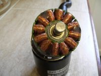
Internal Hall mod top view.JPG

You can just see the three Hall sensors set into slightly widened stator slots and glued in with epoxy.

I hooked everything up, only to find that the motor ran as rough as a badgers arse. The thing sounded dreadful, would trip the controller if the throttle was turned too fast or any sort of load was applied. Not only that, but it sounded like it had a misfire at some speeds, with the controller apparently just cutting out for a fraction of a second, fairly randomly. I suspected a dodgy sensor connection, or a bit of interference, so hooked it up to the 'scope. All the Hall signals looked fine, no matter what I did with wiggling wires or whatever, so it didn't look as if the problem was a poor connection or interference.

The motor is stock, so still connected as delta. This made me wonder whether my good fortune with all the other motors might have been because they were all connected wye. Unfortunately, I didn't want to reconfigure this one to wye, as I needed the higher Kv from delta to get the spindle speed I was after. I decided to do an experiment with variable Hall timing to see if this made a difference, using the idea that gwhy! had for fitting Halls. It was an hours work to make up a simple PCB to hold three sensors at the right spacing:


plus another half hour this morning to mod the milling machine motor mounting plate to hold the PCB:
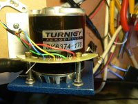
Hall sensor board.JPG

After a bit of playing around, I found that the roughness and cutting out problem was indeed caused by the Hall timing being out. This motor doesn't like running on internal sensors at the neutral position, as I needed to shift the timing by around 10 degrees from neutral (physical, ~ 70 degrees electrical) to find a point where the motor would run smoothly and accelerate cleanly .

It seems that fitting the Halls externally may well be the best way to do it for bigger, delta connected, motors, so this might be a useful tip for those looking to add Halls to standard, unmodified, outrunners.

Jeremy
 
Back
Top