
That's what it seems to me. There is a steel bar with slots cut in it. The magnets are bonded edgewise into the slots and are set below peripheral surface of the iron. So, the wide poles are iron and the narrow ones are the magnets. Does that make sense?
You are using an out of date browser. It may not display this or other websites correctly.
You should upgrade or use an alternative browser.
You should upgrade or use an alternative browser.
Adding sensors to a Astro 3210 motor
- Thread starter JEB
- Start date
Cool. I've thought about doing it that way before. That should really keep the magnets from flying out.
I wasn't sure if you built the poles like that if they would be limited by saturation. I wonder what kind of steel it is?
Is the goo stuff hard like epoxy?
I wasn't sure if you built the poles like that if they would be limited by saturation. I wonder what kind of steel it is?
Is the goo stuff hard like epoxy?
fechter said:I wonder what kind of steel it is?
Is the goo stuff hard like epoxy?
The steel's quite hard, that's all I can say
")
The goo is hard, too......
bigmoose
1 MW
One last question, I promise! :wink: How many magnet poles, and how many iron poles, & total poles, just to be sure they add up? 
8 of each - 16 in totalbigmoose said:One last question, I promise! :wink: How many magnet poles, and how many iron poles, & total poles, just to be sure they add up?
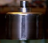
Well... Looking at this rotor in the light of day.... I'm not sure my initial interpretation was correct....
The surface on each of the wider pole pieces differs and the way the surface is pitted at the corners looks more like a sintered/cast product....
The surface on each of the wider pole pieces differs and the way the surface is pitted at the corners looks more like a sintered/cast product....
Thanks for the pictures Miles, always nice to know what the inside of stuff looks like! I am sure they will give all our motor designers here some food for thought.
I am sure that most people here have a good idea about what hall sensors do.
But just for fun , here is a very short clip I made showing the operation of a latching type of hall sensor.
[ Edit: hall sensor is Honeywell SS411A ]
http://www.youtube.com/watch?v=qr2QtTzuiaw
[youtube]qr2QtTzuiaw[/youtube]
Sorry etard, ---I didnt have a blue one :| .
Burtie.
etard wrote:
Maybe you could connect a blue LED that turns on each revolution too!! :lol:
I am sure that most people here have a good idea about what hall sensors do.
But just for fun
[ Edit: hall sensor is Honeywell SS411A ]
http://www.youtube.com/watch?v=qr2QtTzuiaw
[youtube]qr2QtTzuiaw[/youtube]
Sorry etard, ---I didnt have a blue one :| .
Burtie.
How high RPM can you keep up with using halls ? ( this may be a very dumb question, i apologize in advance if it is.. ) hub motors < 1000 rpm, RC motor 8000+
gwhy!
100 kW
Ypedal said:How high RPM can you keep up with using halls ? ( this may be a very dumb question, i apologize in advance if it is.. ) hub motors < 1000 rpm, RC motor 8000+
My setup runs nice at 10k so I don't think there will be a problem with switching speed..
TylerDurden
100 GW
With that space, would Luke's optical system be as good or better? (Gary mentioned this idea)
http://endless-sphere.com/forums/viewtopic.php?f=28&t=14477&start=0
http://endless-sphere.com/forums/viewtopic.php?f=28&t=14477&start=0
MitchJi
10 MW
Hi Y,
Different question but somewhat related. Justin said that the controller that he took on his cross Canada trip (that works in either sensored or sensorless modes) would not work in sensorless mode on most RC motors due to speed.
Ypedal said:How high RPM can you keep up with using halls ? ( this may be a very dumb question, i apologize in advance if it is.. ) hub motors < 1000 rpm, RC motor 8000+
Different question but somewhat related. Justin said that the controller that he took on his cross Canada trip (that works in either sensored or sensorless modes) would not work in sensorless mode on most RC motors due to speed.
johnrobholmes
10 MW
We run three slot motors past 50k with sensored RC car setups, and I have spun 12 slot sensored motors past 12k. I don't think the hall effect sensor will be the limiting factor on commutation speed, moreso the controller's max commutation rate.
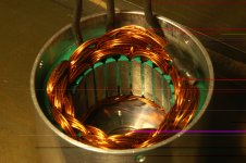
I now have some pictures of the sensor unit fitted to a double shaft 3220 motor


I will wire it all up and test the motor in both Delta and Wye configurations and post the results when I get time :| .
Still looking at embedding some similar implementation inside the end-cap, not there yet tho.
Burtie.
I will wire it all up and test the motor in both Delta and Wye configurations and post the results when I get time :| .
Still looking at embedding some similar implementation inside the end-cap, not there yet tho.
Burtie.
methods
1 GW
-methods
drewjet
10 kW
Nice.
I was just playing with my 3220. I took the end cap off, took the rotor out and put it into the endcap. I then held a hall sensor (I only have one but ordered from mouser some more) between the endcap and the rotor and it clearly switched on and off as the rotor rotated using the magnetic force coming out the side of the rotor. I don't see why a simple plexiglas holder couldn't be easily made to hold 3 of them at 30 degrees and wired up.
I do have a question as to timing, how do you know where to put them in relation to the magnet? And does it make a difference if it is delta or wye?
I was just playing with my 3220. I took the end cap off, took the rotor out and put it into the endcap. I then held a hall sensor (I only have one
but ordered from mouser some more) between the endcap and the rotor and it clearly switched on and off as the rotor rotated using the magnetic force coming out the side of the rotor. I don't see why a simple plexiglas holder couldn't be easily made to hold 3 of them at 30 degrees and wired up.I do have a question as to timing, how do you know where to put them in relation to the magnet? And does it make a difference if it is delta or wye?
gwhy!
100 kW
Hi Drew,
As long as the hall sensors switch cleanly ( a scope is the only real way of viewing the signals also motor needs to be running at full speed when viewing these signals ) as each of the magnets passes then this should also work. The placing of the halls is not important as long as the halls have the correct spacing and the whole group of halls can be rotated to find the correct timing spot. From some of the test on a outrunner motor there was a very slight timing shift between Delta and Wye but in the real world this timing shift did not effect the running of the motor I was testing with. If there is enough magnetic leakage from the end cap ( I think it may be pushing it abit due to the magnetic fields pointing in the wrong direction ) this will make things so much easier because it would be one less rotating thing to go wrong. I think its a very good solution What Burtie has done and should work a treat for any motor with the same magnet count.
As long as the hall sensors switch cleanly ( a scope is the only real way of viewing the signals also motor needs to be running at full speed when viewing these signals ) as each of the magnets passes then this should also work. The placing of the halls is not important as long as the halls have the correct spacing and the whole group of halls can be rotated to find the correct timing spot. From some of the test on a outrunner motor there was a very slight timing shift between Delta and Wye but in the real world this timing shift did not effect the running of the motor I was testing with. If there is enough magnetic leakage from the end cap ( I think it may be pushing it abit due to the magnetic fields pointing in the wrong direction ) this will make things so much easier because it would be one less rotating thing to go wrong. I think its a very good solution What Burtie has done and should work a treat for any motor with the same magnet count.
gwhy!
100 kW
Burtie said:I now have some pictures of the sensor unit fitted to a double shaft 3220 motor
View attachment 1
I will wire it all up and test the motor in both Delta and Wye configurations and post the results when I get time :| .
Still looking at embedding some similar implementation inside the end-cap, not there yet tho.
Burtie.
I know its only in development at the moment but I think the spinning disk with the mags on could go in a recess on the inside of the hall mount, that way you will have no moving parts on the outside of the motor... Just a thought. If this arrangment works well ( I don't see any reason why it shouldn't ) I would not even bother trying to mount the halls inside the motor.
Edit: Or just a round spacer with a round PCB on the end with the halls, that will be a really nice solution as the pcb will make the whole process a lot easier to wire up and also may make the whole assembly thinner.
kfong
100 kW
You can use an optical version of it, just a disk with patterns and optos to sense them.
drewjet
10 kW
Ok so I got my hall sensors from Mouser http://www.mouser.com/Search/ProductDetail.aspx?R=SS41virtualkey67810000virtualkey785-SS41 I hooked them up with the chamfer facing up neg at center, pos to the left and signal to the right. I can't get them to turn on. I tried 4v 6v 8v 12v. I have a hall from an old motor and it works just finejust like that. I tried 6 of them and none worked.
Am I doing something wrong, did I get the wrong ones. or did I get a bad batch?
Am I doing something wrong, did I get the wrong ones. or did I get a bad batch?
drewjet
10 kW
No I don't have a resisitor on the signal lead.
So just add a 1K resistor inline with the signal leg?
So just add a 1K resistor inline with the signal leg?
methods
1 GW
No - there is no active output from this sensor
Think of the hall sensor as a BJT
The collector is the signal lead
The emitter is tied to ground
When the magnetic field is present it runs current into the base and connects the collector to the **** (edit emitter)
Long story -
You need to "pull up" the signal line
This means that you need to tie a 1K resistor between 5V and the signal line
This will output 5V - then when the sensor becomes active it will "pull down" the voltage to 0V
-methods
methods
1 GW
BTW: If at any time you accidentally tie +5V directly to the signal line it will destroy the sensor. As suggested above, the current must be limited to 20mA
5V / 1k = 5mA
That is why a 1K resistor was suggested. Enough current to bias the sensor and raise the noise floor but not so much that it overheats from too much current.
If you use higher voltage - like 10V - you must also use a higher resistance
10V / 2K = 5mA
Make sense?
-methods
5V / 1k = 5mA
That is why a 1K resistor was suggested. Enough current to bias the sensor and raise the noise floor but not so much that it overheats from too much current.
If you use higher voltage - like 10V - you must also use a higher resistance
10V / 2K = 5mA
Make sense?
-methods
Similar threads
- Replies
- 8
- Views
- 639
- Replies
- 10
- Views
- 677
- Replies
- 5
- Views
- 766
- Replies
- 17
- Views
- 6,313