• Howdy! we're looking for donations to finish custom knowledgebase software for this forum. Please see our Funding drive thread

Air Cooling my x5

For the perimeter holes I like to use a multiple of the number of bolt holes, so none of the exhaust vent holes get too close to the bolt holes. I also place them as close to the perimeter as physically possible without cutting into the inside edge of the retaining lip.

Go ahead and write inside the cover, which is which for left and right, and think the angles through several times before actually drilling. A center punch to make a divot so the drill bit doesn't walk when starting the hole is a huge help.

Here's my latest covers with one side intake and other side exhaust in an effort to get more air through the 50mm magnetic gap, but I'm undecided on whether the reduced total flow is worth it. Note that the blades are bolted and epoxied with some surface prep of both the blades I cut from AL sheet and the cast AL cover. With bolts I never have to worry about one coming off and ruining the motor, and the epoxy means a blade could never start rattling. I think the intake side needs another ring or 2 of 12mm holes, but that's the wire side and I'm not reharnessing the motor to drill more holes until I'm sure the ventilation is choked off at the intake. I debated about 5 blades or 15, and decided to start with just 5. I can easily add 10 more to the exhaust side, since that cover is easy to remove.
SuperV with Hubmonster inside covers.JPG
 
John in CR said:
itchynackers said:
I would suggest being a bit more diplomatic in your responses.

I'd suggest not starting crap with a smart ass post that includes me as a target.

Settle down Francis. There is nothing in there that isn't factual. Where did I start a smart ass post please? A target of what? I'm just tired of you belittling people for their cooling efforts. Tired of the "mine is better" type responses. Tired of the "youre all doing it wrong" type responses. Shall I list the posts? The list is long.
 
For the perimeter holes I like to use a multiple of the number of bolt holes, so none of the exhaust vent holes get too close to the bolt holes. I also place them as close to the perimeter as physically possible without cutting into the inside edge of the retaining lip.

Thanks for the tip Jhon (keep away from bolt holes). Originally I was going to do 24 1/4 inch holes on outer perimeter, seems like 27 1/4 inch will be the way to go.... Although I notice in your pick it looks like you've done 45 smaller holes (what size?) is this for any particular reason or do you think 27 a bit larger will do...
I'm also wondering how important you guys think matching total intake diameter of intake holes to outer holes is. I'd think that as long as there is at least the same amount or more in outer perimiter holes should be fine. On the other hand making it a bit harder for air to come out may cause more air circulation.... any opinions on this. Sorry if I'm asking things that have already been answered, this is a long ass thread. I've gone thru a lot of it but not all for sure.

Go ahead and write inside the cover, which is which for left and right, and think the angles through several times before actually drilling. A center punch to make a divot so the drill bit doesn't walk when starting the hole is a huge help.

I've marked both sides with arrows for direction they spin in. My intake holes will be angled opposite from arrows like shown on this web page http://sites.google.com/site/shelbyelectro/motors/mods/ventilating-a-hub-motor. I'll be drilling straight holes first and then using dremel to do angleing much easier than drilling at an angle. I'll use hammer and nail to start up holes hopefully this will be enough....


Ok so as of right now Gonna go with 12 1/2 inch holes for intake and 27 1/4 inch for out as close to edge as possible same on both covers. I'll be watching kids all week so not much riding to be done anyways, so any suggestions on different hole size, amount of holes, variations beetween covers, or location of inner circle will be much appreciated.

Thanks
Fred
 
Fred,

Be careful on the intake holes that you don't weaken the cover too much by getting them too close together. My pic above are covers for a larger diameter motor and that material near the axle is about 1/2" thick. Still I did weaken it by half, and the side covers support the bike. I realized afterward that I should have gone with 2 rings of fewer holes for the intake.

For the angling, that aluminum is really easy to work with. As the bit starts really digging in then I lean the drill bit over. Use the dremel afterward to clean up the tapers and make things nice and smooth. I have no science to the number of holes, though I typically do more than you mentioned. You can make up for it by elongating them and getting a refined shape with the dremel. I did angled slotted exhaust vents once with a dremel using cutting discs, and though it looked nice, it was a crazy amount of work and used up stacks of cutting discs.

Here's a pic of what I did with a 9C. Those angles were with a drill, and I only used a round file to clean a few of them up afterward.
9c cover inside.JPG
 
That's some crazy thick casting in the middle of those hubs John! I guess being made for scooters they're designed to take a heavier load. Did you ever weigh one ?

What are your thoughts on having both intake and exhaust holes on each side cover ? I tend to have intake on one side and exhaust on the other. I also have mixed feelings on the size and placement of the holes. I usually do it the same as you (albeit with fewer, bigger exhaust holes) but part of me says go with bigger holes right over the windings to have more air blowing directly over the hot spot and to allow more heat to radiate out when going slowly (or stopped)
 
itchynackers said:
Where did I start a smart ass post please?

Did you forget about typing this "Be prepared for John to tell you that you're a big idiot and his way is the only way."

itchynackers said:
I'm just tired of you belittling people for their cooling efforts. Tired of the "mine is better" type responses. Tired of the "youre all doing it wrong" type responses. Shall I list the posts? The list is long.

Please start a new thread and send me a link to this long list. Be sure to include those specific instances where I belittled people. What it sounds like is that you got your feelings hurt about my criticisms of a ventilation approach that you copied. It's not my problem that you guys didn't do any research, and that the methodology can't be supported by arguments that withstand scrutiny.

Forgive me for realizing that the air inside a hubbie is spinning in a circle, and that air has mass, so if you put intake holes toward the center and exhaust holes at the perimeter, then flow will obviously take place unless you allow it to be disrupted. Avoiding disruptive turbulence, enhancing the flow, and directing it in a way that increases the convective heat transfer coefficient has been my focus. Now that others are trying to improve upon it, I'm sure we'll see some new and better approaches.

John
 
Hyena said:
That's some crazy thick casting in the middle of those hubs John! I guess being made for scooters they're designed to take a heavier load. Did you ever weigh one ?
The covers are heavy, especially the side with the huge moto disc brake mount. The bike weighed 40kg including batteries last time I put it on the scale. I bet the motor and wheel are half of the weight.

Hyena said:
What are your thoughts on having both intake and exhaust holes on each side cover ? I tend to have intake on one side and exhaust on the other. I also have mixed feelings on the size and placement of the holes. I usually do it the same as you (albeit with fewer, bigger exhaust holes) but part of me says go with bigger holes right over the windings to have more air blowing directly over the hot spot and to allow more heat to radiate out when going slowly (or stopped)

Until Hubmonster I've only done dual sided exhaust. I like the idea of intake on one side and exhaust on the other if it means getting flow through the magnetic gap, which is why I'm trying it. I haven't been able to get it past slightly warm at the magnet backing ring, and it doesn't look like I have enough controller to get it much more, so I'm up in the air right now regarding a preference.

I've got a pretty strong opinion about big holes in general. They don't allow you to get to the very perimeter, so I doubt much air can get through the gap. I proved to DocBass in his X54 thread that radiation is low enough to be ignored at these temps. My biggest problem with holes at the windings is that the flow is going to take the path of least resistance, so I see much of the air flowing along the side cover and out the holes, bypassing the end windings on the way out.

Instead of holes I put fan blades there. The idea behind that is to direct air away from the cover where it will do little good and at the stator. At the very least those blades, which are within a few mm of the end winding must push a quite turbulent flow at the windings. Even at just 25mph that puts a blade passing close to every point on the end windings over 2,000 times per minute, which must add a lot of turbulence there. Turbulence is critical to good convective heat transfer. It's not like a liquid such as water or oil where it only needs to touch the heat source for really good heat transfer. Air requires a turbulent flow just to get decent heat transfer. The blades are probably a significant part of my success with passive ventilation. I've put some kind of blades in all of them so far. For some reason I didn't take a pic of the 9C covers after I put the blades. Here's one of the covers of the motor (equivalent to a 2 turn Xlyte HS40) my son has been using for the past year and for the last month or so really blasting up the mountains at high power.
Big hub venting 1 inside of right side cover the intake.JPG
 
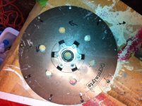
had to start drilling :D i figured id start with just 6 intake holes first after jhons warning not to weaken cover to much heres the pics...
image.jpeg
image (2).jpeg

So 12 half inch holes seems like it would be to much (or not?), i could do 6 smaller 3/8 or 5/16 inch holes beetween them :roll: . still on the fence about how many holes and size for out holes, jhon you make a great point that the smaller the holes the closer to the edge i can get providing more air flow over stator..... :|

ok, little break then ill go ahead and drill same 6 holes in 2nd cover get dremmell out and give some more shape to angles

Thanks for input Jhon!!
Fred
 
one cover done, doesnt look to bad in picture :) though up close i could have definatelly done a better job with my measurments in outer perimiter.
45 x 3/16 holes for out 6 1/2 inch for in. Gonna go make measurments on disc side cover for outer holes and start drilling.
Thats a lot of holes on perimiter (hey whats done is done) do you think this is bad for cover structurally, ive noticed theres usually more concern with intake holes being to close....?
on that note, think I should add more holes to intake???? smaller ones in beetween or new circle right below them, or does this seem sufficient?

cover1.jpg
cover1.jpg
anyways of I go to drill some more :D

Fred
 
Yes, I think 6 more intakes, maybe slightly smaller, and closer to the axle. I'd put them on the same 6 lines as the intake holes you have, though I don't know if that really makes a difference. A bit short on the intake area is probably a weakness on the motors I've done.
 
As a former aerospace guy, I have strong doubts about the practical value of tangentially angling the holes through the side covers in the absence of external scoops or vanes. I'm guessing the strongest effect in terms of through flow will be from center to edge due to centrifugal force, though the hub doesn't really turn all that fast.

It might be most effective to have a decent size scoop fixed to each fork leg, or to each side of the frame, that ducts air into a series of holes near the armature as they rotate by. An approach like that would make fan-forced air easier to implement, too. Heated air could then escape through any or all of the other holes, with no need to entrain the air passing across the surface of the side cover.

Chalo
 
Chalo,

The air inside is already spinning, the holes at the exhaust aren't the blades like for a squirrel cage fan. They're angled in that manner to reduce the negative influence of the air outside as each hole starts at zero speed relative to the outside world when the hole is lined up with the tire contact patch, and accelerates in an arc to it's fatest speed 180º from there and decelerates back to zero on the way back down the other half of the arc. The mod isn't for the rated power crew, but instead for those running higher power and speeds, and a 20cm diameter centrifugal blower can move a lot of air even at just a few hundred rpm, and relatively small flow makes a huge difference compared to the stock sealed motor with hot air inside that must transfer the heat through the outer shell to the outside world.

Of course there's nothing wrong with scoop-like blades at the intake other than the increased potential of scooping grit and sand into the motor. I left my option open to doing exactly that on the first one I ventilated in case the cooling effect fell short. It worked well enough for me that I haven't bothered with scoops.

If my latest version falls short, because I want to take it to pretty extreme power, the motor is too difficult after my wire harness mod to remove the intake cover, so instead I plan to add one large stationary scoop to the bike frame that would funnel air toward the ring of intake holes. This would increase the air pressure there outside of the intake holes, and prevent air from flowing fast by the holes. Both of those effects should help create more flow without increasing the chances of small debris entering too much.

Doubters can doubt all they want, but when I've got identical motors, one sealed and the other not, running at the same voltage in the same size wheel at the same speeds, there is no doubt. Loaded down only enough to push consumption at about 70wh/mile the sealed motor gets hot enough to concern me because I can't hold my fingers on the surface between the spoke flanges for more than a few seconds. Loaded down much more for the same climb, the ventilated motor consumed 167wh/mile, and at the top was only slightly warm between the spoke flanges. We waited for a minute or two and the temp didn't rise and we couldn't feel hot air rising from the upper vents, so the stator couldn't have been terribly hot either.

That's proof enough for me, and actually better than only measuring and comparing stator temps, because that's just part of the system and the magnets have a lower heat threshold than the windings. Better cooling won't save a motor pushed too far into stator saturation, or bogged down to too low a speed on hills, so avoid those situations.

John
 
It might be most effective to have a decent size scoop fixed to each fork leg, or to each side of the frame, that ducts air into a series of holes near the armature as they rotate by. An approach like that would make fan-forced air easier to implement, too. Heated air could then escape through any or all of the other holes, with no need to entrain the air passing across the surface of the side cover.

that's a pretty good idea
 
auraslip said:
It might be most effective to have a decent size scoop fixed to each fork leg, or to each side of the frame, that ducts air into a series of holes near the armature as they rotate by. An approach like that would make fan-forced air easier to implement, too. Heated air could then escape through any or all of the other holes, with no need to entrain the air passing across the surface of the side cover.

that's a pretty good idea

Yes, I missed that part of the post on the first pass, sorry Chalo. In PMs one of the guys mentioned something just like that which get more air going into the centrifugally vented brake discs of F1 race cars. Bring the route of that structure toward the intake area from below, and greatly reduce the chances of foreign matter bouncing in.
 
Here's how ventilated drum brakes in old race motorcycles did it:

norton%20manx%201946%20005.jpg

(it should be fairly obvious which parts stay stationary and which move.. scoop at the front, mesh vent near the shoe linkages).

Overall, they're an excellent study for hubmotor users on a number of levels. Large diameter hub that generate a lot of heat...sounds familiar 8)
 
voicecoils said:
Here's how ventilated drum brakes in old race motorcycles did it
Ah, good point!

triton_005.jpg


f250f.jpg


DrumBrake.jpg

Interestingly all seem to have just the one large opening or cluster of holes/slots in one spot

Alternatively something like this is something that could be made aftermarket, as a complete cover replacement.

Ducati%20rear%20back%20plates%20-%20%20art3027.jpg
 
None of those holes are angled. It'll never work (sarcasm).
 
remember that that will be rotating ;) (probably pointing out obvious).

I would really love to do some custom side covers for say my cromotor. I don't know if it will ever get hot, though. If you guys want to juggle some cad around, I wouldn't mind CNC milling out some covers for any of you guys to try... I have a lot of extra time in the lab this summer. I could make some pretty damn pretty covers, too... :)

If any of you have covers that are off blown motors, but are covers that others on ES could use, I could also spiffy them up
 
Back
Top