Alternative Bike Friction Drive on Rim

I have to agree with Fechter on this. If there is any way to avoid a reduction, you should take it. I would suggest that my experience with friction drives counts for something. Running two motors against the rim is a viable strategy.

One oddity about friction drives is that...they provide the same road-speed regardless of the diameter of the tire you mount them to. In fact, large diameter tires with a friction drive have better hill climbing, compared to a smaller-diameter wheel (the opposite of a hub-motor).

Kepler started out with a single 50mm RC motor, in order to make his kit as light as possible. However, they suffered heat issues on hills, the one place where E-assist was most needed. Once a manufacturer began making a low 149-kV motor in the more robust 63mm diameter RC motors (more copper mass), that became the default choice. The larger 63mm diameter often influenced owners to choose the lower-speed 5S battery packs (18-ish volts), instead of the common 22V 6S.

You, on the other hand...run drive-rollers against the rim, which can be a separate diameter compared to the motor-shell diameter. In this case. I would say that...if you can source a low-enough kV, using two 50mm motors would work. (2X 50mm is better than 1X 63mm)

The only other issue I would warn you about is...the drive rollers need to sit on a shaft that is supported on both ends. Your current configuration may last a long time, but...it is only a matter of time before the shaft breaks, due to a slight bending while running thousands of RPM's.
 
fechter said:
I would try to avoid the gear reduction at all costs. There is a very significant loss in the gears and it adds noise and wear issues.

If the rollers were mounted in such a way as to accommodate several mm of run out in the rim it would be helpful. The assembly can float on pivots.

I have tested the planetary gear reduction drive in a very basic way when I built the trailer tug. I used the same pinion/sun/ring gear setup as what I intend on the friction drive, just because I still have many sets that I can put to work. Running that motor (3536/6 1250 KV of 300 watts free without gear set as opposed to attached to the gear set showed a loss of about 3.5%) I measured the current drain to determine this. Not ideal but a good indicator I think. So for me the loss is not all that hair raising.
 
spinningmagnets said:
I have to agree with Fechter on this. If there is any way to avoid a reduction, you should take it. I would suggest that my experience with friction drives counts for something. Running two motors against the rim is a viable strategy.

One oddity about friction drives is that...they provide the same road-speed regardless of the diameter of the tire you mount them to. In fact, large diameter tires with a friction drive have better hill climbing, compared to a smaller-diameter wheel (the opposite of a hub-motor).

Kepler started out with 50mm RC motors, in order to make his kit as light as possible. However, they suffered heat issues on hills, the one place where E-assist was most needed. Once a manufacturer began making a low 149-kV motor in the more robust 63mm diameter RC motors (more copper mass), that became the default choice. The larger 63mm diameter often influenced owners to choose the lower-speed 5S battery packs (18-ish volts), instead of the common 22V 6S.

You, on the other hand...run drive-rollers against the rim, which can be a separate diameter compared to the motor-shell. In this case. I would say that...if you can source a low-enough kV, using two 50mm motors would work. (2X 50mm is better than 1X 63mm)

The only other issue I would warn you about is...the drive rollers need to sit on a shaft that is supported on both ends. Your current configuration may last a long time, but...it is only a matter of time before the shaft breaks, due to a slight bending while running thousands of RPM's.

Hi, unlike Kepler I don not use the motor's shaft. The output shaft of the box is 10 mm. Running on two 10 x 19 x 5 bearings.
2 x 50's will weigh more than one 63. I opted for a motor 42 MM so I can try and keep the weight below 500 gr for both drives. The gear set is a single stage 4:1 ratio and total length of the box is a mere 12.5 MM.

If you look at my 3D model, the diameter of the motor is 42 MM and the drive wheel is 45 MM. That is about as large as I think is OK for a seat stay inconspicuous drive. Length of the whole drive is 60. MM
 
I was not concerned about added losses, I just think that once you commit to using two motors on a friction drive, you can use the smaller 50mm diameter units, and the cost + bulk of a reduction is not necessary.

If you order a large lot, you can have any currently available motor wound to any kV that is possible. All that changes is the diameter of the wire, and the number of wraps per stator-tooth.
 
"Computer trials" will only get you so far, and will just take up your time as well as not highlighting some of the unforseen practical issues.
You will have to build a prototype and test it thouroughly to see where the problems are.
 
Hillhater said:
"Computer trials" will only get you so far, and will just take up your time as well as not highlighting some of the unforseen practical issues.
You will have to build a prototype and test it thouroughly to see where the problems are.

Very true.
 
Sure this will slip in the wet. Before I wrapped my motor in sandpaper, it would slip like mad against the tyre even when the road was just a little bit wet after a few raindrops. Metal on rubber vs. rubber on metal - I doubt there is difference.

Motor brake/regen can be done by using the rear brake cable to force pull the swingarms towards each other. Although I don't think braking will be very effective, mainly due to the 1C charge current limit of the battery.
 
cozy35 said:
My design goal is to use a max of 22.2 Volts and limit that to 12 Amp battery to yield a max of 250 Watts of power and to be able to maintain 25 Km/H on a 10% incline, un-assisted.
Totally unrealistic. Going 25kph up a 10% hill requires, from experience, 700W and a lot of effort from myself. And I am just 60kg.
 
Folken said:
cozy35 said:
My design goal is to use a max of 22.2 Volts and limit that to 12 Amp battery to yield a max of 250 Watts of power and to be able to maintain 25 Km/H on a 10% incline, un-assisted.
Totally unrealistic. Going 25kph up a 10% hill requires, from experience, 700W and a lot of effort from myself. And I am just 60kg.

You are correct about the 10% -700 W. I erred and had that figure in mind for the off road mode. I actually calculated 250 watt for a 3% incline. My bad.
 
cozy35 said:
Just thinking that old style rim brakes don't really fade all that much when riding in rain so i think the rim friction drive should be OK.
That depends on the design of the pads, at least some. The pads scrape the rim surface "clean" of water and gunk, which a roller will not do--it will instead roll over the water and gunk just like it does the rim itself. But except for where the pressure of the roller against the rim is sufficient to have time to force the stuff out from between the roller and the rim, that stuff will keep the roller surface from effectively pushing on the rim itself.

It's exactly like a tire on the road--only where it can push the stuff off the road and actually touch tire to road does it make contact, and transfer power.


Mid mounted motors suffer from dirt and much build from the front wheel. Up high as on the seat stay is about a safe as can be place.
Other than whatever is carried up there by the tire. ;)
 
OK, so after some more toiling in my mind the suggestion of spinningmagnets makes perfect sense. Discard any ideas of reduction drives and rewind/reconfigure the motors for the required KV. This will make a much lighter and cost effective drive.

My thinking is as follow":

I have a couple of off the shelf Turnigy 3536/6 out runners that produce 500 Watts and 1250KV @ 14.8 Volts/34 Amps. These are wound 6 turns delta. To achieve the desired 360 KV that I want I would have to rewind these with half the strands and double the turns and also in WYE connection. WYE connection will reduce KV by dividing 1.73

1250 KV @ 6 turns
625 KV @ 12 turns
Delta to WYE will lower KV to 361
The volume of copper remains the same and so should the power output also remain at 500 Watts. "I hope I have it right"
 
Here's a similar setup:
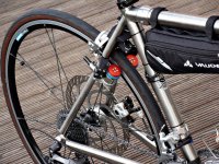
http://www.velogical-engineering.com/velogical-velospeeder.en

velospeeder_velogical_sdc10357_v2_lr.jpg

Depending on the motor position, it may also be possible to change the diameter of the rubber drive wheel to effect gearing change within a range.
In the one above, it looks like the drive wheel is solid with just a rubber ring on the edge. This would make replacing the rubber easy. They claim:
no slipping when starting up (even when wet), no braking effects at higher riding speeds.
 
fechter said:
Here's a similar setup:
http://www.velogical-engineering.com/velogical-velospeeder.en


Depending on the motor position, it may also be possible to change the diameter of the rubber drive wheel to effect gearing change within a range.
In the one above, it looks like the drive wheel is solid with just a rubber ring on the edge. This would make replacing the rubber easy. They claim:
no slipping when starting up (even when wet), no braking effects at higher riding speeds.

Wow.. that is expensive. Looks like they use lipo batteries in that frame bag.
 
Folken said:
Just curious: are you going to sell this? I'm sure Velogical has patented this type of drive already.

Bike drives is just an interest for me. I may offer parts as it would ease the cost of CNC machining etc. If I have to get the motor custom wound for my use I would most probably have to take 100 or more. It is still early days and I still need to get a prototype going first. I wonder what part Velogical would have patented? What they have is no rocket science or new invention but suffice to say that it looks pretty impressive.

From Velogical's webiste bout the patent...
"The trick by which this patented invention is different from all other friction wheel drives in the history of the bicycle, is the geometric arrangement of the swing axle with the engine mount and the solution for the power transmission at the friction wheel. Wheel circumference, rotation speed, ventilation are further accompanying factors, through which it is possible to build these engines so miniaturized small."
 
OK, so what I have been doing so far...

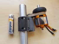
The 3D printing is done and I have trial assembled one drive with the parts. I managed to make a sandwich carbon fiber swing arm to save some weight, but I think an Aluminum 2024 machined part would be far superior in cleanliness and looks. (Anodized)

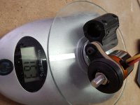
Weight comes in at 163g each with the smaller (To be rewound) 3536/6 motors. I intend to rewind these to 12 turns and also connect in Wye (Star) to get the desired 360 KV.

Picture take with AA battery for size comparison.

20160922_123530.jpg

Weight assembled is 163gr.

20160922_123922.jpg
 
fechter said:

Fwiw, I test rode this at Aaron's Bicycle Repair in Seattle. Aaron had it mounted on a their spartan parts-bin shop bike. The unit's power was impressive for such small motors, in my opinion it pulled like a 250-watt geared hub. Motor whine was a bit louder than a geared hub. The package would be a nice boost on a lightweight roadie. Prior to the ride, I did some reading about it and assumed the motors flipped against the rim from torque like the designs from Adrian/Kepler/Hidden Power/Add-E, etc. The Velo does not work that way. Instead, it uses a handlebar lever and cable setup to pull the motors inward. That added complexity was disappointing [to me], but it was functional and the drive wheels didn't slip while climbing. IMO, this rim-drive idea gets more points than a tire drive.
 
silviasol said:
Never though 3d printing would be strong enough hold a bolted clamp setup like that. I need to get one!

3D printed stuff is not nearly as strong as required. It was just for trial fitting and concept. I find it better to visualize with parts in my hand than on screen. At this moment I am making Vytaflex molds to make the parts using two part poly infuse casting with carbon reinforcing. I will later have them CNC'd out of 2024 Al for top quality anodized parts.
 
emco5 said:
fechter said:

Fwiw, I test rode this at Aaron's Bicycle Repair in Seattle. Aaron had it mounted on a their spartan parts-bin shop bike. The unit's power was impressive for such small motors, in my opinion it pulled like a 250-watt geared hub. Motor whine was a bit louder than a geared hub. The package would be a nice boost on a lightweight roadie. Prior to the ride, I did some reading about it and assumed the motors flipped against the rim from torque like the designs from Adrian/Kepler/Hidden Power/Add-E, etc. The Velo does not work that way. Instead, it uses a handlebar lever and cable setup to pull the motors inward. That added complexity was disappointing [to me], but it was functional and the drive wheels didn't slip while climbing. IMO, this rim-drive idea gets more points than a tire drive.

I am going for the inertial engage swing in method as with Kepler/Adrian,Add-E & Hidden Power's way. The cable pinching complicates the installation. I believe that with the correct pre-set "bite-in" angle it will overcome slippage, but I still think it will suffer in the wet.

Velo also uses two controllers to power both motors. I am sure on controller would work OK in parallel. I have seen some hobbyists do this on boats and planes.
 
Back
Top