First "scientific" tests today, but I forgot to put the PDA/speedo on it so I have only rough guess on how fast I went at any point, and not sure of average speeds.

Basically the motor will let me shift up two or three gears higher than I could normally pedal at, if I work as hard as I usually do for pedalling. That's a few MPH faster (don't know exactly how much) than I would usually ride pedal-only. I did test it a bit here and there to see what it would do without pedalling, but not enough to really stress anything yet.
Bike is running on a 36V 9Ah D-type NiMH pack (from a Giant suede-e brand bike), about 12 pounds. I haven't been able to fully charge it yet, as my 60V power supply is still not fixed, so all I have is a 40V supply that maxes out at 43.2V. (I use these because they're current-limited, so they won't blow up the batteries by feeding too much current while the difference in voltage is still high; they essentially run in constant current all the time until the voltage creeps up to match the output of the supply). ***
2.5 mile trip to work at typical straightway speeds of 12-16MPH, with around a dozen or more full stops and starts for traffic controls:
42V starting rest voltage
40.47V finish rest voltage
34.32V minimum trip voltage
16.35A peak
22.4Wh (about 9Wh/Mile)
578W peak
0.538Ah
2.5 mile trip home from work at typical straightway speeds of 12-16MPH, with around a dozen full stops and starts for traffic controls. The light was also powered during this trip (had to put electrical tape over it to keep *every single light source* from turning it off!), which takes roughly 70mA extra:
40.68V starting rest voltage
38.64V finish rest voltage
32.01V minimum trip voltage
18.64A peak
23.9Wh (about 9.5Wh/Mile)
616W peak
0.652Ah
During the trip to work, hard accelerations dipped a couple of LEDs down on the power meter, but coming home they all went out and the "battery warning" light came on (didn't cut out, though, dunno what LVC is on this thing, if it has one). So I tried to be gentler with it on the homeward trip, though I could more freely go faster than during the day, since there was virtually zero traffic at night.
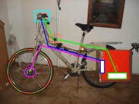
I don't know if all that wire length has anything to do with it, but here's the current wiring layout.
View attachment 1
Power runs from battery in the box thru watt meter on top tube to light/keyswitch/power meter unit on the bars, then back to controller in the box, back up to the motor on the front wheel. That's a long trip for an electron, so they're probably worn out by the time they get there, and can't do much on the little quantum hamster wheels.
So I think I'm going to alter the way the system works. Right now it's designed so that the keyswitch physically disconnects main battery power from everything. What I am going to do is make the keyswitch connect power to a relay that will then power the controller. The keyswitch will only directly power the light module, which takes less than 100mA total, so I can completely remove all the heavy-gauge wires (the vacuum cleaner cord), and run a single thin 3-wire cable instead.

The watt meter will come out entirely from the visible instrumentation, and only be in the box, wired between the battery and the rest of the bike. Since I have the LED power meter on there it's good enough for telling what my power situation is, and I only need the watt meter for collecting test data.
Two of the wires to the light module will be power and ground from the battery, just like they are now. Ground goes right to the light module board, while power goes to the keyswitch. Just as now, other side of the keyswitch goes to the light module board. In addition to this, the third wire will go from that side of the keyswitch back to the relay coil.
The other side of the relay coil will be wired to watt meter output ground. The relay contacts will switch the positive lead from the watt meter output to the controller. Controller ground will go to the watt meter output negative lead.
Turning the keyswitch on will then engage the relay, connecting power to the controller. The keyswitch will directly apply power to the light/meter/etc. inside the handlebar unit.
The watt meter will always be on if the battery is connected, so I can keep the data "live" during rides even when I stop and lock it up somewhere, so I can collect the data when I get home instead of having to write it all down at each stopping point, or losing it should I have to emergency-turn-off the motor for any reason.
This whole thing removes about 8 feet of wire from the power path of battery to motor. Ought to make some difference to performance, but I don't know how much, since the currents drawn are pretty low.
The relays themselves will come from the same UPS I pulled my CrazyBike2 batteries from (and the large filter caps for the 2QD). There are several of them and I will probably parallel at least three of them, to be more sure of power handling capabilities. Their coils are only 24VDC, so I will put a resistor and zener on there to limit to that voltage.
*** I have an idea for charging the packs faster and "safer", but haven't had a chance to do the wiring needed for it. Basically I take three 2/4-cell AA NiMH fast chargers I have, and wire up little 4-cell-at-a-time 5-wire harnesses to the packs, a little like balancing plugs. Matching connectors on the chargers, soldered to the points the AA battery clips connect to on their boards, run out the side of the cases so I can also still use them for AAs. Then I can charge 12 cells at a time in the pack. There are 32 cells in the 36V pack, so I charge up 12, then 12, then 4 + 2.
I'll probably use old AT-keyboard DIN connectors for this, as I have a pile of old dead motherboards with those on them, plus a pile of old dead keyboards. I also have a bunch of female DIN connectors in a box somewhere, from my old MIDI-cable-making days, but haven't seen them for literally a few years. I could also just cut some of my old DIN extension cables in half, and that would be even better, since I do not have to wire any connectors up--I just solder in the wires from the cable itself on there (females on the batteries, so the pins can't get shorted by something falling into the connector while riding). But this would "waste" several male connectors, as I only need three of those, but need 8 female connectors for the 8 sets of four batteries in the 36V pack. More if I use the same method on the 24V pack.
At about 400mA (the limit for two of the chargers), they'd charge up the 9Ah pack in about a day and a half if I really totally drained it.
Assuming I remembered to swap the chargers around at the proper times, or have them where I can see the lights on them that show they're done. One of the chargers can do closer to 800mA, so it can charge it's 4 cells faster, and thus get 2 banks of 4 done while the other two only get one each.
This also will be safer on the batteries, as these have charge controllers built in specifically to keep the batteries safe.