Аn angle of hall sensors

Kirill

100 W
Joined
Dec 10, 2019
Messages
137
Hi everyone!

How to measure the angle of hall sensors?

The manufacturer of the DD motor Suringmax SR35HD 1500Watt claims that in this motor the Hall sensors have the angle of 120 degrees.

But the motor with such the angle value doesn’t work. The bike simply doesn’t move. Only idle speed with clicks.

Self-learning of the controller gives a different angle from 59 to 70.

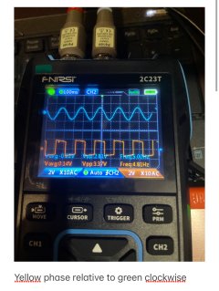
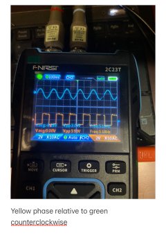
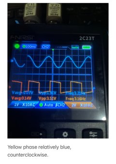
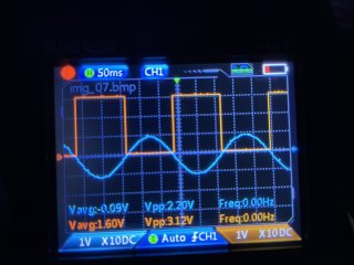
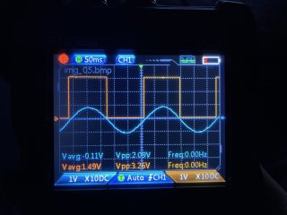
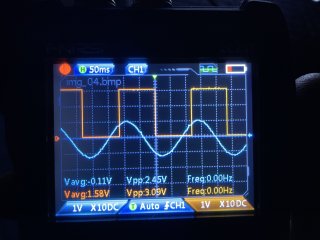
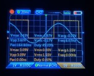
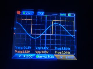
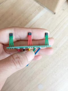
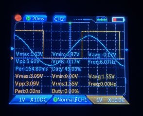
I decided to measure the angles using an oscilloscope.

Here are the measurements. But I don't know how to interpret them.
 

Attachments

  • IMG_1659.jpeg
    IMG_1659.jpeg
    1.7 MB · Views: 12
  • IMG_1658.jpeg
    IMG_1658.jpeg
    1.7 MB · Views: 12
  • IMG_1657.jpeg
    IMG_1657.jpeg
    1.5 MB · Views: 12
IMG_1665.jpeg
 

Attachments

  • IMG_1665.jpeg
    IMG_1665.jpeg
    1.4 MB · Views: 6
  • IMG_1664.jpeg
    IMG_1664.jpeg
    1.5 MB · Views: 5
  • IMG_1663.jpeg
    IMG_1663.jpeg
    1.5 MB · Views: 5
  • IMG_1664.jpeg
    IMG_1664.jpeg
    1.5 MB · Views: 5
  • IMG_1663.jpeg
    IMG_1663.jpeg
    1.5 MB · Views: 6
Two more
 

Attachments

  • IMG_1669.jpeg
    IMG_1669.jpeg
    1.6 MB · Views: 4
  • IMG_1668.jpeg
    IMG_1668.jpeg
    1.9 MB · Views: 4
Try the 60 degree setting.

I use FOC controllers and they autodetect/manage this for me, What controller are you using?
 
Try the 60 degree setting.

I use FOC controllers and they autodetect/manage this for me, What controller are you using?
Yes right. Have to set 60 degrees. Auto-identification works.
I use Votol EM50-4.
But the question is different.
The motor manufacturer claims that the angle of the hall sensors is 120 degrees.
We see that this is not so.
The controller manufacturer claims that the motor must have a hall sensor angle of 120 degrees.
And now I'm trying to get to 120 degrees.

I'm waiting for delivery of the board with Hall sensors like the QS motor with which Votol works without problems.
On both sides on the edges Y3141 and in the middle G3466. Looks so.
 

Attachments

  • IMG_1842.jpeg
    IMG_1842.jpeg
    88.5 KB · Views: 5
You can't tell the angle by looking at one hall signal.
If the motor hall angle is 120 degrees, there will be no positions where all three hall signals are high. Two at the most.
If the motor hall angle is 60 degrees, there will be some positions where all 3 are high or all low.

Below diagram is from this thread by Tommycat:
Hall sensor issue, after switch

1735489010896.png
 
What you are saying is all clear and understandable.

I calculated the offset angle of the hall sensors to be 65 degrees.
Here are the calculations:

1. Angular frequency:

ω = 2πf = 2π * 6.07 Hz ≈ 38.12 rad/s

2. Angle of displacement in radians:

φ = ω * shift = 38.12 rad/s * 0.03s ≈ 1.14 rad

3. Angle of displacement in degrees:

φ (degrees) = 1.14 rad * (180/π) ≈ 65.35 degrees

The data for the calculations was obtained from this oscillogram.
 

Attachments

  • IMG_1669.jpeg
    IMG_1669.jpeg
    1.6 MB · Views: 4
But now I want to know where is the 120 degrees promised by the manufacturer?
Why does the motor manufacturer claim that the hall sensor angle is 120 degrees?
But it is doesn't so.
Why does the controller manufacturer claim that the motor should have the hall sensor angle of 120 degrees? And doesn't guarantee correct operation at 60 degrees.
 
The hall sensors are placed in 120 degrees (electrical degrees, not physical) relative each other, then there is another thing called offset which is how the sensors are aligned with the stator. The offset is often 60 degrees because they are placed in between the stator winding.
 
But now I want to know where is the 120 degrees promised by the manufacturer?
In this STM paper, there is a whole chapter (8.3) about hallsensor reading. It might help for understanding. You have to keep in mind, that the 120° are valid for an electrical revolution, not a physical.

1735647440519.png

The position relatively to the BEMF varies from hardware to hardware, depending on where the Hallsensors are placed.
In the EBiCS firmware, the motor is driven by a constant id in open loop during the autodetect routine, so you can get the corresponding angle for each of the 6 transitions from one Hall state to the next.

1735647716919.png

regards
stancecoke
 
Last edited:
Hi Kirill,

Been following along from the start, totally enjoying your oscilloscope images.

But now I want to know where is the 120 degrees promised by the manufacturer?
Would you post a picture showing the outputs of all three hall sensors in a cycle?
No offense to your formula, but this would easily show the sensor degree orientation. As well as looking great in my thread, with your permission. :)


But it is doesn't so.
If you truly have 60-degree output.

What is your total magnet count?
Post a picture of your sensor's locations.
Are they all the same number?
Are they all facing the same direction?

I ask because the difference between 60 and 120 can be easily changed by inversing one of the sensor's outputs.
Typically, on a PCB board type installation, this will be the middle sensor.
And could be done in a couple ways...
1) Use a hall sensor type with inverted output.
2) Pointing the face of the same type of sensor the opposite direction will invert the output.

Wrong board installed, or sensor types?


Regards,
T.C.
 
Hi Kirill,

Been following along from the start, totally enjoying your oscilloscope images.


Would you post a picture showing the outputs of all three hall sensors in a cycle?
No offense to your formula, but this would easily show the sensor degree orientation. As well as looking great in my thread, with your permission. :)


If you truly have 60-degree output.

What is your total magnet count?
Post a picture of your sensor's locations.
Are they all the same number?
Are they all facing the same direction?

I ask because the difference between 60 and 120 can be easily changed by inversing one of the sensor's outputs.
Typically, on a PCB board type installation, this will be the middle sensor.
And could be done in a couple ways...
1) Use a hall sensor type with inverted output.
2) Pointing the face of the same type of sensor the opposite direction will invert the output.

Wrong board installed, or sensor types?


Regards,
T.C.
Don't know if you read what I wrote but it's quite common to have 120 degrees between the hall sensors but 60 degree offset.
 
The hall sensors are placed in 120 degrees (electrical degrees, not physical) relative each other, then there is another thing called offset which is how the sensors are aligned with the stator. The offset is often 60 degrees because they are placed in between the stator winding.
Yes, but didn’t quite understand the meaning. Would this statement found online be accurate and clarify your post?

”Then hall sensors are 120 degrees electrical apart. Mechanical placement can be within 60 degrees physically. It is the electrical displacement that matters.”
 
Yes, but didn’t quite understand the meaning. Would this statement found online be accurate and clarify your post?

”Then hall sensors are 120 degrees electrical apart. Mechanical placement can be within 60 degrees physically. It is the electrical displacement that matters.”
Yes!
 
Just a clarification of the electric degree: The 120 degree means it's one hall sensor on U,V and W phase. One electric revolution is when a magnet pole pair (north plus south) has passed all three phases, 120+120+120= 360 electric degrees.
 
Last edited:
Would you post a picture showing the outputs of all three hall sensors in a cycle?
No offense to your formula, but this would easily show the sensor degree orientation. As well as looking great in my thread, with your permission. :)
Hi!
Only one oscillogram shows the offset.
The remaining two phases looks like this.
Here attached the instructions.
 

Attachments

  • oscilloscope instruction.pdf
    1.1 MB · Views: 10
  • 2024-11-27 18-10-14.jpeg
    2024-11-27 18-10-14.jpeg
    1.4 MB · Views: 1
  • 2024-11-27 18-10-05.jpeg
    2024-11-27 18-10-05.jpeg
    1.5 MB · Views: 1
If you truly have 60-degree output.
Yes. Instruments cannot make mistakes.
Self-identify sets from 59 to 70 degrees.
Of course I set it to 120 degrees. But of course the bike doesn't go, although the no load speed is high.
 
Pointing the face of the same type of sensor the opposite direction will invert the output.
This is how it works in the Shengyi X2 motor. I copied the hallsensor PCB to attach the Kclamber cassette torquesensor connector to the board and wondered, why the pin order of the center sensor is reversed....

regards
stancecoke

1736016303818.jpeg


This is one layout of the original PCB:
1736016682651.png

on a another X2 motor, I found a slightly different layout:
1736016850851.png
 
Last edited:
Are they all facing the same direction?
Yes of course. That's the point, all three are in the same direction.

I have used several different hall sensors over the time.
All three sensors were identical at the time of installation.

1) Factory version: factory board and three 4451H
60 degrees.

2) factory board and three 41F
60 degrees.

3) blank board and three Y3141
Doesn’t work.

4) factory board and three SS413F
60 degrees.
 
But why 60 degrees in reality I can’t understand.
I can't understand, why you are relying on your scope measurement. Just check, if the hall sequence is 5-1-3-2-6-4 or backwards 4-6-2-3-1-5.
If not, turn the center hall sensor by 180 deg. and check again.🤷‍♂️
 
I can't understand, why you are relying on your scope measurement. Just check, if the hall sequence is 5-1-3-2-6-4 or backwards 4-6-2-3-1-5.
If not, turn the center hall sensor by 180 deg. and check again.🤷‍♂️
Why should I not trust the oscilloscope?
I have practical confirmation of these measurements.
Do you think auto identification also lies?
When I manually set the controller settings to 120 deg., the bike wouldn't move at all.
Yes, the motor wheel can rotate, but only in the air without load.
But once the wheel hits the ground, can only feel a slight twitch.
 
Back
Top