Any risk adding inductance between controller and motor?

John in CR

100 TW
Joined
May 19, 2008
Messages
14,954
Location
Paradise
So I've got my ferrite cores, 4.5"OD, 2.25"ID, .75" thick that I'm going to wind with 8ga wire. I'm shooting to add approx. 50uH to 75uH to each phase in an effort to help protect my last remaining higher power controller from my controller eating motor. Even at quite moderate current every controller I've tried with these motors has run quite warm, and with each phase consisting of 2 turns of 8-9ga wire on 17 teeth, I'm convinced that low inductance with low resistance is to blame. I'm certainly not going to add resistance, so after a couple thousand $ worth of controllers over 2 years, I'm finally going to follow Fechter's advice and add some chokes in front of the motor.

I wanted to check before I do something stupid and make sure I'm not doing something that introduces a new risk. What if these DIY coils have some variance in their inductance? Could that create some kind of imbalance and blow the controller?

While I'm at it, I'd like to understand what the added inductance does that makes it an easier load for the controller, and are there detriments other than hopefully slight losses in the added coils? How will it affect performance. I understand that inductors slow the flow of electricity, and in other applications they act as low pass filters. On its own, I take it that a controller would send square pulses of DC current due to PWM, and if the current is allowed to flow freely, the abruptness of on/off of high currents is hard on the controller, like turning a facet on and off very fast repeatedly and you hear the water hammer effect in the pipes. Then the added inductance slows the transitions and rounds off the corners so to speak, resulting in a smoother wave form instead of one that is like the bill of a sawfish.
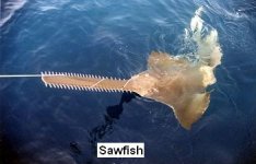
Sawfish.JPG
 
John in CR said:
I'd like to understand what the added inductance does that makes it an easier load for the controller

here's what should be a reasonably close analogy that may help.

have you ever hooked up an audio amp designed for an 8 ohm load with 2 ohm speakers?
in your case what you're attempting to do is more like attaching half ohm speakers or even less.
basically what you want is to impedance match the load with the power source.
i think you can see how the rest of it goes but just to be complete.

simply by adding 3 more 2 ohm speakers in a series string your amp won't go splodey on you.
now the additional 2 ohm speakers could just as easily be replaced by a 6 ohm resistor in series.
same goes for your motor, you could use resistors rather than inductors.
but in both situations resistors would be a huge waste of power & space requiring big expensive high wattage power resistors.
so to waste less power (less than a resistor would but not quite as good as having extra speakers) another option is to use an appropriate value inductor in place of the power resistor to function as a load matcher.
either way the amp will be in it's happy place.

pls remember an analogy is for entertainment & illustrative purposes only & does not constitue proof.
also not intended for use as a pry bar or a punch.
void where prohibited by law.
 
Toorbough ULL-Zeveigh said:
John in CR said:
I'd like to understand what the added inductance does that makes it an easier load for the controller

here's what should be a reasonably close analogy that may help.

have you ever hooked up an audio amp designed for an 8 ohm load with 2 ohm speakers?
in your case what you're attempting to do is more like attaching half ohm speakers or even less.
basically what you want is to impedance match the load with the power source.
i think you can see how the rest of it goes but just to be complete.

simply by adding 3 more 2 ohm speakers in a series string your amp won't go splodey on you.
now the additional 2 ohm speakers could just as easily be replaced by a 6 ohm resistor in series.
same goes for your motor, you could use resistors rather than inductors.
but in both situations resistors would be a huge waste of power & space requiring big expensive high wattage power resistors.
so to waste less power (less than a resistor would but not quite as good as having extra speakers) another option is to use an appropriate value inductor in place of the power resistor to function as a load matcher.
either way the amp will be in it's happy place.

pls remember an analogy is for entertainment & illustrative purposes only & does not constitue proof.
also not intended for use as a pry bar or a punch.
void where prohibited by law.

Thanks T U-Z,

Great example, but where do I find the controller that likes the low load like some of my little tube amps love 2ohm speakers? I had trouble finding much on the subject, but one discussion of some robot wars guys back in '99, indicated that for brushless motors they were having to lower the PWM frequency for low inductance motors. Shouldn't the PWM frequency be an adjustment option with our programmable controllers?

Also, if I was blowing amps like controllers, then I'd want to understand why the low ohm load of my favorite speakers was killing the amps.

I guess if the chokes waste too much energy (get quite hot), then I could do exactly what I'd do with speakers, and lock 2 stators and rotors together and run them in series. I'd much rather run 2 motors in parallel and get a lot more output, just like with speakers.

John
 
I don't think there is much risk. The motor is already an inductor, so the controller is expecting an inductive load.

The problem with low inductance motors is during PWM switching, the phase current can go too high and blow the FETs.
In an inductive circuit, when the FET switch first turns on, the current is zero, then rises over time to eventually reach some astronomically high value that depends on the voltage and DC resistance of the windings. Normal controller/motor setups expect the switch to turn off well before destructively high currents are reached. If the inductance is too low or the PWM switching frequency is too low, the peak current will go higher than you want. Changing the PWM frequency is one way to avoid this, but also introduces more switching losses. Adding inductance will add some resistance losses, so there is some brain-melting math you can do to optimize the efficiency.

In your case, making the controller survive is more important than a few percentage points of efficiency. I don't see how too much inductance (within reason) would cause a problem.

There are ways to measure the inductance and peak current, but the test equipment is going to be pretty expensive.
 
Thanks Fechter. So the PWM current limiting isn't fast enough to avoid phase current spikes from peaking above what I have the phase current limits set to? Then the extra inductance slows the current rise just enough to give PWM time to do it's current limiting job? I'm trying to understand why Arlo1's controller can survive crazy high currents that I know my same controller cannot, and it's not just about beefing up the traces.

Regarding the efficiency loss, I'm only looking at a couple of extra feet of 8ga with a few wraps around a toroid, so if I get anything other than very insignificant losses with the added inductance, then it's gotta show up as heat coming in those inductor cores. If I've got extremely high current spikes, their duration is so short that I'm not getting any extra performance, just heat in the wires and controller. If I can eliminate them with the extra inductance, then I might even get over to the plus side in terms of efficiency with reduced heat at the controller and in the wiring.
 
I think Fechter explained it well and it fits with what I have observed about placing simple inductors in series with pretty purely inductive devices. I have simulated it in LTspice where it is easier to leisurely observe what happens, and it looks well-behaved and clean.
 
Thanks quys. We machined the square corners off of the mags, I mean cores. I hope to have the overhauled motor ready for reassembly tonight, and test it tomorrow weather permitting.

John
 
I've got the bike up and running with my DIY toroidal coils wound with 6 turns of 8ga using a 4.5" OD magnets from some old speakers.

My issue now is I don't know whether it's doing any good or not. The only thing I notice is that the motor seems to make a bit less noise during take-off. The AC current of the phase wires hasn't degaussed the magnets yet. The mags/cores haven't gotten warm at all.
 
Lol This is why I started the inductance thread it explains all of this. I also did dyno tests showing different amounts of inductance.
There is no harm other then possible lower efficiency from added resistance of the wires and connections and the inductors take up space and add weight to the bike. I am trying to find more inductance for colossus and its not easy!!!

So far the only way colossus will run with a 24fet with out blowing the controller was will some external inductance! That's unless I put the phase and battery amps so so low I might as well walk!
 
John in CR said:
I'm trying to understand why Arlo1's controller can survive crazy high currents that I know my same controller cannot, and it's not just about beefing up the traces.
My traces from the controller that produced the SPIKE in my avatar pic are hollow copper pipe soldered to the traces to help cool the fet legs and the fets themselves!
The same set up was/is also on my bmx with my x5 which has 255uH inductance and .18 ohms resistance so it turns into a space heater at this power level but the controller is safe because the resistance is so much higher then the controller resistance and MORE IMPORTANLTY the inductance is so hi the controller can leave the fets turned on so long and let the amps creep up slowly where as a motor like colossus will cause huge spikes and the controller doesn't shut off the fets fast enough! If you ask bigmoose he has a inductance spreadsheet he posted on my thread so you can play with numbers so you can see in a graph whats happening and how fast. As well you should get a inductance meter they can be got for cheep on egay.... Mine serve their purpose and seem accurate enough for what you and I are working on!
 
I guess I'm going to have to spring for one. Then I can at least know how much inductance I'm adding, but more important for everyone else is experiment with some smaller cores. The smaller ferrite ring magnets that I have are stronger than the larger ones I'm using, so they may be made of a better material for cores.
 
motor current going through a few turns on a ferrite toroid will saturate it for sure I would think. If you got an iron powder toroid maybe not - or maybe you want a saturable reactor?
It's quite tricky to do inductor development at home, with a mystery mag circuit all you can do is measure the L with 5 or 10 turns on then remember L proportional to N^2.
To predict when it will saturate you need lots of core info, mag circuit A, L and material properties (most ferrites start to saturate at ~0.3T).
Or a beefy supply (battery?), oscilloscope & current transducer & look at the shape of the amps over a few microseconds..... amps go up linearly when it's an inductor, then shoot up when it saturates and it's not any more....
 
With TexasPyro's comment, "won't last long" and BobC's "and it's not anymore", do I have to worry about these cores turning into shrapnel or something. I've been going slow with it and haven't really given it the juice, but nothing warm. Isn't saturation going to be a gradual thing like it is with the iron in the stator? Isn't heat going to be the sign that I'm approaching saturation?
 
Isn't saturation going to be a gradual thing like it is with the iron in the stator?
Motor saturation is gradual with respect to amps because of material properties & the fact that the magnetic circuit area varies a lot. Gradual with respect to time, forget it - instantaneous ;^) Yes many ferrites have a rounded BH curve or softish saturation. Saturation doesn't hurt anything, just means there's less L
There are toroids that will take a lot of amp turns - the powdered iron I mentioned is a possibility. Ferrites need an airgap to do it (which toroids don't have)
 
These cores are just magnets off of speakers. My only other material choice to be able to wind toroidal coils with large gauge wire were things like:

Coils of thin gauge steel wire- I worried about eddy currents
Magnetite+epoxy molded into doughnut shapes- Seemed closer to iron powder which requires twice as many turns as good ferrite cores.

Regarding the air gap, I may have obtained one unwittingly. My phase wires are magnet wire, and I worried about scuffing the varnish or breakage if I had to wind the coils multiple times, so in addition to wrapping each in a phase color tape I also slid each one into clear plastic tubing before winding. That gives me several mm of spacing between the wire and the core.

Here are my cores with a centimeter ruler for size reference
Toroidal cores for Blue.JPG

Here are the coils wound with 6 turns of 8ga wire before securing them under the seat of the bike.


If more air space is desirable, then maybe I should remove the zip ties that force a tighter wind.

Just to be clear in my understanding. Without testing that I can't do, I have no way of knowing the current limit of my coils. When I pass that limit, does the inductance go to zero, or do I still get a portion of the inductance? Going to zero surely isn't intuitive, and would be the worst possibility for me, since at my system's highest currents is when I need the extra inductance the most. So far I've turned it up to 100A battery side, which puts my phase current limit at 250A with no ill effects.

With a very low target inductance in the range of 50-100uH for each coil is saturation really a concern? As saturation is approached wouldn't it manifest itself as warm or hot cores?
 
Hey John I think your winds need to be tight together. I unwound the Hybrid iron/air core inductors that another member kindly sent me and I can show how when the wires are spaced from each other it has less inductance and closer gives more.
 

Attachments

  • 027.jpg
    027.jpg
    70.5 KB · Views: 1,441
  • 028.jpg
    028.jpg
    75.7 KB · Views: 1,441
  • 002_renamed_18102.jpg
    002_renamed_18102.jpg
    69.4 KB · Views: 1,441
  • 003_renamed_32015.jpg
    003_renamed_32015.jpg
    63.8 KB · Views: 1,441
Thanks Arlo1, but I must be missing something. From your pics I see that fewer turns is less inductance, and the difference isn't linear. From what I read about toroidal coils, evenly spaced around the core is the way to go. The difference in the flux path is the reason. On mine it's contained within the circle, which is why fewer turns are required. With a straight coil the flux path is out the ends to wrap around back to the other end, so loose turns will have early leakage at that point.

My big concern at this point is saturation, while I wait on my inductance/capacitance meter to arrive. Have you ever seen your cores get warm or hot?
 
John in CR said:
Thanks Arlo1, but I must be missing something. From your pics I see that fewer turns is less inductance, and the difference isn't linear. From what I read about toroidal coils, evenly spaced around the core is the way to go. The difference in the flux path is the reason. On mine it's contained within the circle, which is why fewer turns are require. With a straight coil the flux path is out the ends to wrap around back to the other end, so loose turns will have early leakage at that point.

My big concern at this point is saturation, while I wait on my inductance/capacitance meter to arrive. Have you ever seen your cores get warm or hot?
From what I have seen they will only get hot if you use wire that is to thin causeing more resistance!
You are probably right about evenly spacing your coils. The meter will help you explore all this!
 
Arlo1 said:
The meter will help you explore all this!

The wait is painful. I beefed up the controller that I ran without issue in the past at 100A, and even ventilated it. It's my last one that can handle more than 60A, so I can't afford to blow this one. Now I'm playing the waiting game for controllers and a meter, though I am going by an electronics repair shop in the morning with a core and some wire. Hopefully they have a meter to at least check inductance of some different turn counts, and see if that tubing makes any difference.
 
John in CR said:
Arlo1 said:
The meter will help you explore all this!

The wait is painful. I beefed up the controller that I ran without issue in the past at 100A, and even ventilated it. It's my last one that can handle more than 60A, so I can't afford to blow this one. Now I'm playing the waiting game for controllers and a meter, though I am going by an electronics repair shop in the morning with a core and some wire. Hopefully they have a meter to at least check inductance of some different turn counts, and see if that tubing makes any difference.
You should take your motor to that shop too so you can get them to test it. The motor is the item you REALY need to know the inductance of!
 
John in CR said:
Arlo1 said:
The meter will help you explore all this!

The wait is painful. I beefed up the controller that I ran without issue in the past at 100A, and even ventilated it. It's my last one that can handle more than 60A, so I can't afford to blow this one. Now I'm playing the waiting game for controllers and a meter, though I am going by an electronics repair shop in the morning with a core and some wire. Hopefully they have a meter to at least check inductance of some different turn counts, and see if that tubing makes any difference.

It's especially difficult since the new 8ga motor harness has the motor running cooler than ever. I don't know if maybe the coils are helping too, but this sealed motor is begging for more power, and that's not even my big motor.
 
Arlo1 said:
You should take your motor to that shop too so you can get them to test it. The motor is the item you REALY need to know the inductance of!

Good idea. I have 5 and only 2 are on bikes right now, so bringing a spare for measuring is easy.
 
a speaker magnet is probably not a good material to make an inductor - it is a "hard" magnetic material used to make a permanent magnet, its BH loop will be like a big open square. To make a linear inductor you want a BH loop that's like a single angled line through 0,0 (no enclosed area). I#ve never made an inductor this way and would be quite interested to know its properties, but I expect high core losses because of the energy contained within the BH loop. The air gap I'm talking about is actually a break in the magnetic circuit, i.e. a break in the toroid. E cores and C cores that come in 2 parts make it easy to add an airgap, by clamping a sheet of non magnetic material between the core halves. If you look at high DC current inductors you can often see a plastic spacer in there.
When saturated the inductance does not go to zero, you still effectively have an aircored coil there, but it drops a lot, probably by a factor similar to the relative permeability of the core material (100 to 1000 - who knows)
these guys explain it better than me....
http://www.powermagnetics.co.uk/documents/powdercore/pcDesign.pdf
 
Did you demagnetise the magnets John? If not the magnetism will lower the inductance!
 
Back
Top