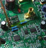
APL's V4 Cruiser Build.

Just joking on the internals of my controller, (but there could easily be some assembly line mess up in there.)

I remember seeing a review where somebody said that they're controller came with reversed Pos and Neg sticker and colored plastic
terminal rings. Look close at this web picture and you can see the Neg marking on the case but the red sticker and lug.
(Opposite of mine.)
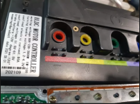
Controller reverse pos.png

So, somebody hooked up the main power backwards! :shock: Now we know why the transformer is blasted off the board. :lol:
 
APL said:
Look close at this web picture and you can see the Neg marking on the case but the red sticker and lug.
I hate it when that happens. Who do you believe? The color or the symbol? :shock:
 
Goldenmotor did that with one version of their Magic Pie, some years back; there's a number of threads about this somewhere around here. They used black wire for the battery positive cable, and red wire for the negative. Instead of fixing this, even knowing what would happen, they shipped them out anyway.

Eventually they started putting little stickers on the wires to show the black was positive and red was negative, but they KEPT MAKING THEM WITH THE WRONG WIRE COLORS instead of just doing it the way everyone else has always done it. :roll: :bolt: :kff: :flame: :lowbatt:
 
It might be worth opening up your controller just to take a look anyway. Sometimes there is an obvious problem.
 
OK, I have a few bad-weather days this week, so I might as well take a look around inside and see what can be seen, I'd love to find something wrong.

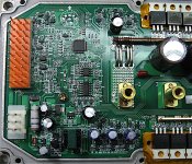
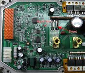
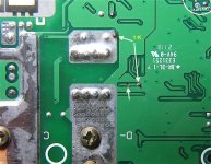
Top pins.jpg
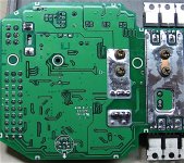
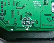
Bottom pins.jpg
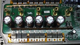
Top Fets.jpg
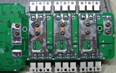
Bottom Fets.jpg

Came apart easy enough, silicone seals on the pins and lugs. Looks like a well built 18 fet to me. Everything is soldered nice enough
and nothing is loose, caps, transformer, etc. A few mini-resistors missing here and there, but I see the same ones on the web photos.
It's nice to see the main pin connections and serial port labeled underneath.

For what it's worth,. big resistor is brown green brown gold, the fets are SKY Silicon SKST04 9N08N, and it has 470uf 100v caps.

I looked over every solder joint with a magnifying glass and couldn't find anything that looks funky or sketch at all, but your eyes are better trained, so if anyone want's a closer look at something, I can zoom in on it.
 
Nothing jumps out at me. The four shunts look well-soldered-in; unless they are the wrong ones (too high a resistance, causing higher voltage output for the current thru them vs lower resistance ones), misleading the controller into the wrong current output, then they're fine.

The other things that could cause a controller to output less current than it should would be the buffer/amplifier circuitry between the shunts and the MCU. I don't know where that is but would guess it is the U3 circuit array, if U3 is an op-amp (perhaps lm741 or similar). But you can't know what values anything is supposed to be; it could have just one wrong resistor in that circuit to cause this problem.

With no obvious hardware problems, I suspect it is much more likely a setting; perhaps it is set to the wrong shunt value, or it is set to the wrong current limit.

I don't know which is hte programming connector; I suspect it's the one marked AIO that isn't populated. The pad arrangment reminds me of the old Macintosh serial connector
https://www.google.com/search?q=apple+serial+connector&newwindow=1&tbm=isch but I'm not sure that's actually the right one. (but if you had to, you could solder in any connector you wanted, just wiring it in with a cable soldered to the board instead of directly soldering the connector itself into the board). A search for the markings on that connector give this link (which is not for this controller but rather for one that looks like an old Curtis brushed type)
http://m.doczj.com/doc/bf16486151.html
and this is the cache
http://webcache.googleusercontent.com/search?q=cache:Sf7MD8Exm-8J:m.doczj.com/doc/bf16486151.html+&cd=1&hl=en&ct=clnk&gl=us
and the translated relevant part is
Figure 5: RS232 serial port wiring diagram
Figure 5 shows the standard RS232 interface, the controller can be configured and calibrated by connecting with the computer through the converter provided by us. Please use a standard DB9 serial extension cable to connect the controller to the computer (non-crossover extension cable).
RS232 and PCB port wiring method:
CN005 pin definition CN006 pin definition
1#: GND 1#: GND
2#: empty 2#: GND
3#: SWDIO 3#: CANL
4#: SWCLK 4#: CANH
5#: NRST 5#: empty
6#: empty 6#: LUTX
7#: empty 7#: LURX
8#: LURX 8#: empty
9#: LUTX 9#: empty
That controller uses a standard DB-9, but the fact that the names show up the same means it is a serial port of some purpose, and the most likely one is for programming. :)
 
Amazing build, absolutely beautiful.
I think the frame is so beautiful that is it "a shame" to hide it behind black paint. Maybe I'm wrong but I feel like a flashy color could have been really awesome too and make it stand out even further.
Maybe you could also use some carbon vinyl on the battery covers, would definitely look cool, everything looks better with carbon, for some reason (or even better, use real carbon fiber, but the wrap is a really good low cost alternative).

In any case it's really, really impressive. Great work mate!! :bigthumb: :bigthumb: :bigthumb: :bigthumb: :bigthumb: :bigthumb:
 
The controller layout looks pretty nice. I don' t see any obvious problems.

APL controller Top pins.jpg

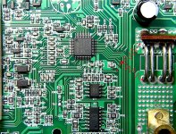
The 4 manganin wires are the shunt resistor. In the old days, we would dump some solder across them to lower the resistance and increase the current limit. The signal from the shunt goes over to the MCU or possibly through the small chip next to it first. I can't read the chip numbers, but I'd guess there's a LM358 to amplify the current signal before it heads to the MCU input. By adding a potentiometer to one of the amplifier resistors, you can make the current limit adjustable.

I'm sure there's a way to program the current limit, but you would need their programming software and cable interface.
 
What are the numbers on the 3 main chips? 8 leg one, 14 leg one and the mcu?

I'm not going to be much help here, it looks fine, but i am wondering what control topology it has.
 
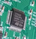
I couldn't see the chip numbers by eye, but when I took another close up you can kind of pic them out. The MCU appears to be a
ST brand, STM32F series I think, but looking it up on the web finds this; https://www.st.com/en/microcontrollers-microprocessors/stm32f0-series.html#overview
Has some interface info, but nothing very useful,.. (if it's even the same chip). I haven't looked up the other smaller IC numbers yet.
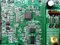
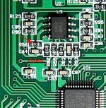
Kinda hard to see, but looks like A425 or S on the 8 pin, and C34 ARC on the longer one.

Yantan chip.png

By adding a potentiometer to one of the amplifier resistors, you can make the current limit adjustable.

Now were talking! I magnified the circuit to get the chip number and help maybe figure out the amplifier circuit, .. programing is probably not going to happen. Are we talking R55? Doesn't appear to be going anywhere.. except over towards the shunt neg.

Closer look.jpg

I don't know which is hte programming connector; I suspect it's the one marked AIO that isn't populated. The pad arrangment reminds me of the old Macintosh serial connector

I magnified the serial solder points, I was thinking maybe the RX and TX connections plus ground, same as the Votol series?
The FTDI module or the PL2303 module and cable from QS might work, but without the software...and it's just my guesswork too.

Serial connect.jpg

Thanks Dui, ni shuo de dui, she rides really good too! :thumb: The vinyl on the side covers is ready for a change anyway, I'll try
out the carbon fiber look this time. :wink:
 
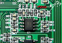
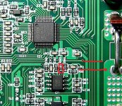
It's kind of hard to trace everything out from the picture, but it looks pretty typical. The 8 pin chip is a version of 358, configured as a X10 amplifier for the current signal. To get a higher current limit, we need to reduce the gain.

APL controller 358.jpg

The resistor labeled R96 appears to be the feedback resistor for the amp, 10k. If you place another 10k resistor in parallel with this one, it should double the current limit. You could use something like a 100k, 10 turn trimmer pot across it to get a good adjustment range. For a fixed increase, we can do the math on the required resistor value.

The alternative approach (possibly easier) is to cut the trace going to R55 (zig-zaggy line) and solder a couple of tiny wires going to each end. Then attach a 1k pot to the wires. This will give a 100% to 200% range compared to stock. This is nicer since the adjustment range will be linear and it looks easier to solder to the ends.
 
Awesome, sounds like a plan.

LM358 and A42S dual amp pin out.
LM358 pin out.png

I'm not familiar with the LM358 Op Amp, but looked around to try to get a better handle on it,.. didn't help much, and sure glad you know this stuff, I would never figure it out,.. oriented the board with the chip notch 'up' to match the pin out.
(Just cause it helps me to figure out what's going on.)

Looks like cutting and soldering the copper trace to R55 is easy enough, I've done it before, but it doesn't appear to be connected to anything on one side. Kind of looks like it goes over to both sides of the shunt on the other side of the board though, so I think I'm starting to get it., shunt's across the amps 5&6 input. Don't see any solder on the trace ends so I guess I'll have to assume these things are pre-welded these days.

Op Amp A42S.png
Shunt crossovers.png

Edit:
Might have a small trim pot somewhere, don't know about 1K but I'll look, otherwise I have to order one. A small resistor would be quicker, and I have crap tons of those. Maybe try a 1K, 2K, or 3K for starters?
 
One end of the trace goes to a via (hole through to the other side). The other end goes to R55. You can use a small flat screwdriver to carefully scrape off the green solder mask around the via and solder a wire there. The other wire can go to the end of R55, or you can scrape off the solder mask on the trace going to it. The ends of the traces will lift off the board easily if there is stress applied, so I like to use very skinny wire to make those connections, then go to the resistor.

You could cut the trace and put a 1k across it and test. This would be 2x stock. I don't think you'll blow up anything, but there's always that chance. For sure you can figure out if it's the controller or the motor itself that is the bottleneck.

If you do this mod and don't see any improvement, I would put it back to the stock configuration.
 
Cheers APL. Can't work out what that c34 thing is. I'm guessing comparator for measuring the phase angle in sensorless mode given the 3 big 10k resistors that seem to be heading off into the power stage. Any ideas fechter?

That's not really helping you though :lol:

That controller is so old tech. MOSFETs didn't change much though so if you can persuade it to try harder... Those skymos things are from crmicro i think i used similar crmicro MOSFETs on my original controller build, worked amazingly well for such cheap (50p each) FETs. I was easily getting 50A phase out of 1 of them in d2pak and you have 3 of them in parallel.
 
I was easily getting 50A phase out of 1 of them in d2pak and you have 3 of them in parallel.
Wow, maybe there's hope yet, look easy to replace too.

I like this style of controller, even though this ones giving me grief, things are laid out nice, and seems to be sealed fairly well. Easy to take apart.. and you got to like that big heat sink slab. But we must persuade it, yes! :thumb:

I have a lot more respect for robots, this stuff is small! It would be easy for some smd's to get mixed up. My smallest resistor looks like a tanker truck on there! :shock:

1K mod (1).jpg

But I got 'er done. I was able to drill out the via, and solder the resistor on both sides of the board, so that's kinda solid,.. and went over to the shunt pad on the other end. Plans change when you start getting in to it, but the deed is done and I can still go back.

Had to cut the crossover underneath.
1K cut (1).jpg

Anyway, the battery's charging, so tomorrow we'll find out if I'm going to get spanked yet again, or if it actually takes off,.. or if the
magic smoke makes a guest appearance. :bolt:
 
Nice work. That should do something. If you don't get the desired result, you can always undo the mod. On one of my projects, I used a small pot on wires and found a spot on the controller housing where I drilled a small hole and glued the pot on the inside. I can adjust the pot on the outside with a tiny screwdriver. The pot is water resistant IP67 or something like that.

Anyway, see what happens and report back.
 
Nope, nada, in fact no throttle at all, spanked again. :| But I know were on the right track. :thumb:

I took it apart and checked everything over with the ohm meter and looked it over good. All checked out, so I soldered a wire across the resistor and tried it out again,.. runs fine, nothing wrong with the circuit.

I'm starting to think we might be going the wrong direction though, and should be going across R55 instead of before it? If they used to put solder across the shunt to raise the resistance, then wouldn't lowering R55's resistance value do the same?

If so, then soldering to the other side of R55 is impossible, but I could probably just remove it and solder it shut, and then increase the resistance by adding another resistor to the one I just put in. Any of this sound viable?

Anyway, I figure 'if' going that direction, it would mean lowering the R55's value to say 500 ohms, to get a 100 percent increase. :?:

R55's value appears to read '01B' , so 1K ohm?. Measured it out 'in circuit' at .982K, so makes sense. My theory is that if I solder R55 shut, with the 1K resistor I have in there have now, then it should act like stock.

Course I could be completely wrong too.
 
Bummer...

There was a lot of guesswork on my part tracing the circuit from a picture. There are traces running under the chip that I can't see. In real life, I would probe the traces with an ohmmeter to see which one goes where. The MCU is looking at the output from the chip and if the value is outside an acceptable range, it triggers a fault and shuts things down.

The old fashioned crude way it to get a piece of 12ga solid copper wire that is about 1/2 the length of the manganin shunt wires and lay it between the and solder it in to lower the shunt resistance.

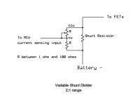
The other way is to place a divider between the shunt and the amp input. A little more complicated but not too bad. This circuit gets inserted where you cut the trace.

2x variable shunt divider.jpg
 
For just a test, you can use fixed resistors. If you use equal resistors, it will double the current limit. As the previous diagram shows, something between 1 and 100 ohms should work. I used 10 ohms.

Sorry for the bad drawing, but below shows one way to hook them up. The junction of the two resistors goes downstream of the trace cut (to the amp input).

APL controller Top pins 4.jpg
 
No problem, it's all trial and error, and I'm up for it. :thumb: I figured the MCU was shutting down from an out of range signal and can probably be changed only so much from the outside. Maybe the 1k is just a little too far out and should be less?

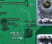
This picture shows the trace connections under the board, from one side of the shunt to R55, and the other side of the shunt to the
R99 / C85 trace. Both 1K resistors.

Closer look.jpg

I can try the divider circuit, but assume that the circuit can give more shunt voltage to R55 than stock? (Unless I'm still thinking backwards), we still need to make R55 somewhere around 500 to 700 ohms instead of 1K to raise the MCU signal V. (or R99)
 
The divider circuit is fairly fool proof. I should have suggested that to begin with. It eliminates any possible offset issues.
Using one fixed resistor and one pot makes it adjustable from stock to 2x stock. Other ratios are possible by tweaking the divider resistors. It also allows you to make two of the connections on the big shunt wire pads which are easier to work on, but you may need a larger iron. I have used this circuit on at least two controller types with excellent results.
 
Finally, sweet success! :bigthumb:

Been waiting a long time to say that. :) The divider circuit did the trick, and I'm up to the 2500w mark now.
(finally broke the old 1300w barrier!)

You've done it fechter, and the old Yantan has been successfully hacked, Thanks! I also want to thank amberwolf, and everybody else that has helped figure this damn thing out for the last month or two, it's been a long time coming. :thumb:
I've really learned an awful lot!

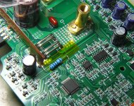
I put in the two 10 ohm resistors, (one across the 1K), and now she runs just about perfect,.. front wheel don't quite come off the ground yet, but that's a good thing. :wink:

Divider resistors.jpg

Now we'll see how long it takes to shell out that freewheel...
 
OK, good result.

You could make it boost a little more it sounds like. If you want to add a pot, you can make it easily adjustable, or another option is a switch that goes between fixed settings. I have something like that on one of my bikes. 3 speed switch that only changes the current limit. Sometimes having a lower limit is useful, like trying to maximize range or limit heating.

Your motor should be fine with 2500w limit on relatively flat ground.

Does that controller have regen?
 
Nice one. I'd never have guessed a controller that size would be shipping with such a low default power setting. Makes me wonder if you could have had luck fiddling with the settings over the comms header.

Any chance of videos of this beast in action?

Can confirm... Assuming Leaf motor is the same as the voilamart available in the UK... It can take plenty of power. Been feeding one 120A up to a ~3.5kW limit and it barely gets warm under standard "ebike quickly through the woods" kinda treatment.

Dunno if I've said this before, but my biggest concern with your design is the tiny cogs on the drive chain. The smaller the cogs the higher the stress on your chain and axles. If you can swap them out for bigger ones, it should generally be kinder to everything. But working is working right?
 
Back
Top