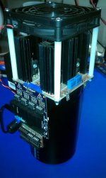
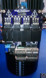
Arlo's power stage Leaf controller runs and drives page 103

A bootstrap high-side supply is basically a charge pump, except it uses the FETs as the switching element rather than a separate switching circuit. It's simple, very effective, and widely used. I have no idea why Arlo hates it so much... All you need is a diode and one or a couple of capacitors. There are certain edge cases where bootstrapping fails, but if you think about it carefully that scenario is almost impossible to encounter in a BLDC application. There are many, many app notes and other documents which describe how to do bootstrapping correctly and how to choose the components.
 
rhitee05 said:
A bootstrap high-side supply is basically a charge pump, except it uses the FETs as the switching element rather than a separate switching circuit. It's simple, very effective, and widely used. I have no idea why Arlo hates it so much... All you need is a diode and one or a couple of capacitors. There are certain edge cases where bootstrapping fails, but if you think about it carefully that scenario is almost impossible to encounter in a BLDC application. There are many, many app notes and other documents which describe how to do bootstrapping correctly and how to choose the components.

I agree, go with KISS :mrgreen:

kiss_2009.jpg
 
Teh Stork said:
Clever - I'll probably roll the same design :)

Couldn't one use a cheap charge pump (200mA, 3-22V) to isolate the 12V? This one is about 1 dollar on mouser.

Edit: After some thinking, I should add; I'm planning to run logic supply voltage at 3,3V - the same as the microcontroller I plan on running. Then I can directly run pwm from microcontroller to driver. Separate hi-side voltage must be added. (look at figure 12B in ir2110 datasheet, my uC max out voltage is 3,3V - but this will be well over the threshold for "1" logic).
A quick look at your charge pump and its only good to 10v so no. (although if you only run 10 or less to everything then maybe)
But who runs everything at 10 or less?? I looked at running 9 volt to the gates with a smaller resister and I am not sure if its a good idea.... It would get me just past the miller plateau but im not sure if its a good idea. Still thinking about it.
Yes you need to run 5 v to vdd on the IR2110 and IR2113 drivers.
I will redo my schematic in the first post so its easier to read soon.
 
rhitee05 said:
A bootstrap high-side supply is basically a charge pump, except it uses the FETs as the switching element rather than a separate switching circuit. It's simple, very effective, and widely used. I have no idea why Arlo hates it so much... All you need is a diode and one or a couple of capacitors. There are certain edge cases where bootstrapping fails, but if you think about it carefully that scenario is almost impossible to encounter in a BLDC application. There are many, many app notes and other documents which describe how to do bootstrapping correctly and how to choose the components.
Simpler then what I have???
Isolated power to the hi side is about the simplest you can get isnt it?
I Choose this layout because I figure its the best...
I dont have to wait for the bootstrap caps to charge ever, I have less components to install and test, my cost is a bit more in parts but when im buisy I save money becasuse my time is worth more then those parts!
 
The reason why people have had troubles with bootstrap circuits is probably because of the choice of capacitor (and/or diode). You can't use an electrolytic IMO. They have too high ESR (and possibly also ESL). I would choose a SMD ceramic. The actual gate driver IC would of course also need a ceramic.

The problem I see with using a generic ("black box") isolated DC/DC is that you don't know how fast dV/dt between secondary and primary it can handle.
 
Arlo1 said:
Teh Stork said:
Clever - I'll probably roll the same design :)

Couldn't one use a cheap charge pump (200mA, 3-22V) to isolate the 12V? This one is about 1 dollar on mouser.

Edit: After some thinking, I should add; I'm planning to run logic supply voltage at 3,3V - the same as the microcontroller I plan on running. Then I can directly run pwm from microcontroller to driver. Separate hi-side voltage must be added. (look at figure 12B in ir2110 datasheet, my uC max out voltage is 3,3V - but this will be well over the threshold for "1" logic).
A quick look at your charge pump and its only good to 10v so no. (although if you only run 10 or less to everything then maybe)
But who runs everything at 10 or less?? I looked at running 9 volt to the gates with a smaller resister and I am not sure if its a good idea.... It would get me just past the miller plateau but im not sure if its a good idea. Still thinking about it.
Yes you need to run 5 v to vdd on the IR2110 and IR2113 drivers.
I will redo my schematic in the first post so its easier to read soon.

"Vout = 2Vin", so you can have your 20v gate voltage :)

Still not certain of what to run - bootstrap seems like the cheapest and best choice...
 
Arlo1 said:
Simpler then what I have???
Isolated power to the hi side is about the simplest you can get isnt it?
I Choose this layout because I figure its the best...
I dont have to wait for the bootstrap caps to charge ever, I have less components to install and test, my cost is a bit more in parts but when im buisy I save money becasuse my time is worth more then those parts!

How is a complete isolated DC-DC converter simpler than a diode and a couple of caps? I suppose if you look at it as a black box it's one component vs. two... but that's an absurdly simple way of thinking that will get you into trouble eventually.

bearing said:
The reason why people have had troubles with bootstrap circuits is probably because of the choice of capacitor (and/or diode). You can't use an electrolytic IMO. They have too high ESR (and possibly also ESL). I would choose a SMD ceramic. The actual gate driver IC would of course also need a ceramic.

The problem I see with using a generic ("black box") isolated DC/DC is that you don't know how fast dV/dt between secondary and primary it can handle.

Bearing is correct that you'll probably only have trouble with a bootstrap if you don't take the time to design it properly. And you're in for a big surprise if you think that you can avoid all the design issues by using an isolated DC-DC. Bearing also hit it right on that there will be some inter-winding capacitance in the transformer that will give you problems if the dv/dt is too high, plus you need to know what the isolation rating is, etc... Your average DC-DC, especially some e-bay cheapie, is not going to be designed to have the secondary ground bouncing between zero and a hundred-some volts.

I promise, there's a reason that you can find bootstrap discussed in so many app notes...
 
I'm a noob on power design, but after reading app notes and more importantly listening to Rhitee05 and Bigmoose and Electroglide, I'm sticking with the boot strap setup in my driver stage. This is what they do.

P.S. Thanks for helping get me started down the right path guys 8) Hopefully my journey (directed at you bigmoose) will have less bumps and even fewer fires and explosions :lol:
 
Sharing this: IRS2334

We're already using ~12ohms of total resistance to limit current into gate. I see IR2110's being used at 8A peak, being rated at 2A. Can these be used to satisfy our switching speeds?

Edit: to the poster below me, why oh why didn't you use film capacitors instead of that huge electrolytic? This paper is a very good read up on capacitor sizing and parameters to look at for different applications.
 
I'm one of the "guests" who's been lurking in the shadows, but I'd like to take this opportunity to make my first ES post and stick my neck out for Arlo.

I recently finished a high-voltage (up to 450 V) high frequency (up to 500 kHz) h-bridge and used DC-DC 1kV isolated supplies to power low-side FET-drivers that drove high side FETs. The isolated side of the supplies moved back and forth just fine from zero to rail voltage, and the signal was passed by an optocoupler. I had several reasons to do this:

1: Drive V(g-s) to -5v to properly turn the SiC MOSFET off in a reasonable time.
2: 9 amps of gate drive current
3: Matched propagation delays for high and low side
4: Safety!! (0.1" isolation barrier between LV and HV sides of the board)

For anyone interested:

IMAG0507.jpg

IMAG0509.jpg

Big cap is here: http://search.digikey.com/scripts/DkSearch/dksus.dll?vendor=0&keywords=495-3672-ND

Arlo, there's nothing wrong with the way you're doing it. Everyone else, if you think he's doing it all wrong, build one and prove that your way is better. Talk is cheap!! :D
 
chbaird said:
1: Drive V(g-s) to -5v to properly turn the SiC MOSFET off in a reasonable time.

A reasonable reason to go with isolated supplies. You could provide a negative gate bias using a bootstrap technique, but the added complexity might make using isolated supplies worth it. Not an issue here since silicon FETs don't gain much from negative bias.

chbaird said:
2: 9 amps of gate drive current

This could be done with either bootstrap or isolated supplies - it only requires a high-current buffer.

chbaird said:
3: Matched propagation delays for high and low side

Also doesn't have any relation to the choice of bootstrap vs. isolated.

chbaird said:
4: Safety!! (0.1" isolation barrier between LV and HV sides of the board)

This might be slightly easier with isolated supplies, but the IR2110 and similar chips are rated for 600V isolation and the packages are designed to make proper spacing possible (not difficult), and you can easily buy 600V diodes for the bootstrap.

chbaird said:
Arlo, there's nothing wrong with the way you're doing it. Everyone else, if you think he's doing it all wrong, build one and prove that your way is better.

Never said he was doing it wrong - isolated supplies obviously work. But they're not the simplest approach, and I'm a firm believer in KISS unless otherwise justified.
 
I just figured once I have a good DC/DC isolated supply. I dont need to know much about it so me being the end user it IS simplier.
I got the idea from two people Luke who I am not sure has a working power stage... And Guru Shane Colton! So I figured when I need to do a -5volt pull down to turn off the IGBTs I have it will also come in handy...
 
Teh Stork said:
Sharing this: IRS2334

We're already using ~12ohms of total resistance to limit current into gate. I see IR2110's being used at 8A peak, being rated at 2A. Can these be used to satisfy our switching speeds?

Edit: to the poster below me, why oh why didn't you use film capacitors instead of that huge electrolytic? This paper is a very good read up on capacitor sizing and parameters to look at for different applications.

Found another one with a internal charge pump that maintains cap charge. 0,5A - 80V input. Intersil FN4220. Cheap too, 4,2 dollars.
 
Arlo1 said:
I just figured once I have a good DC/DC isolated supply. I dont need to know much about it so me being the end user it IS simplier.
I got the idea from two people Luke who I am not sure has a working power stage... And Guru Shane Colton! So I figured when I need to do a -5volt pull down to turn off the IGBTs I have it will also come in handy...

International Rectifier MOSFETS and IGBTs don't need negative bias to turn off fast. Your IGBTs might though.

Here is the app note for an IR2110 driver IC if you are interested. You'll see the buffer circuit I lifted from on page 17, but it's very easy to modify that and seperate the VDD from the VCC/VB voltage supply so you can control your logic 0/1 switching voltages. Should also use larger than 10uF caps on the buffer if you plan to power several paralleled devices, big moose showed examples in my power stage thread of what he calculated as the minimum based off the min gate charge needed.

This may not be what you need, but this app note also explains boot strapping nicely and how to select and calculate the components you'll need.

The floating bucket setup is cool since it provides isolation. All low volt inputs pins on one side, all HV on the other.
 
For those of you who didn't see on the other thread. I got it to turn a motor and now once I get it smother I will scope the powerstage and see how it all looks. Then up the voltage and scope again. [youtube]fDzOdgLpc60[/youtube]
 
This powerstage setup seems pretty good. I think I will make sure I order quality isolated supplies for the big one. But I am realy happy so far. I tested for a good while today and found most my work is going to be in the programing of the controller it self. I think what killed it was the ground for the Lowside drivers slipping off the aligator clips lol

Here is a test at 84v and man this thing sings at ~1/4 throttle.
[youtube]wvnUW37oXLo[/youtube]
 
Looks to me like YOU were doing the singing. :roll: :roll: :lol: :lol: :lol: :lol:

I'm totally impressed with your project. Just wish I understood what you are doing. :roll: :roll: :) :)
 
Harold in CR said:
Looks to me like YOU were doing the singing. :roll: :roll: :lol: :lol: :lol: :lol:

I'm totally impressed with your project. Just wish I understood what you are doing. :roll: :roll: :) :)
Simple. ONE GOAL and that is to build a controller that I have 100% control over.
SO I made it multistage so I can replace parts when needed you know when you pop a fet or two ;)
 
OK so I got it back together with new fets. I have a weird sensor timing issue... I started a programing thread as well http://www.endless-sphere.com/forums/viewtopic.php?f=30&t=36275
[youtube]Olv1YuIqqzk[/youtube]
 
Ok so Im planning to test 6 fets to destruction. Slowly... I want to get this running a motor then load down the motor till The fets cant produce any more and they pop but I need a game plan. All I know is I want to test irfp4468 (100v) irfp4568 (150v) and irfp4668 (200v) to their limits. I was thinking 84v 20s for the 100 volt fets and 30s 126v for the 150v fets and 168v 40s for the 200v fets. Or do you guys think I can gather enough info all at 84v???

I planed to run colossus wound at 1/2 the kv with the 200v fets as compared to the 100v at normal kv so it will be the same rpm at full voltage it should just show me how the fets will survive at the different ratings. I will design a temp monitor for the motor and fets themselves to try to gather all data properly.
 
I have a question what do you guys think about parrellel diodes to the diodes in the fets???
 
Arlo1 said:
I have a question what do you guys think about parrellel diodes to the diodes in the fets???

If freewheeling mosfet heating is a problem: go for it :) Will also reduce diode forward drop some, in turn - reducing some of the heating aswell. You should look into TVS diodes aswell, Colton seems to be into them for some of his hi-specific-power builds. I do not know much about TVS diodes, but they will supress spikes between phases. (mounted between A-B, B-C and A-C in the cart build)
 
Arlo1 said:
I have a question what do you guys think about parrellel diodes to the diodes in the fets???

Thats something I have been wanting to try in practice. I have only simulated it in LTSpice. According to simulations, the switching losses could go down a lot, since there won't be that big current spike from reverse recovery charge in the body diode. This could make it possible to increase switching frequency a lot from the ~20kHz commonly used.

The diode needs to be a very hefty Schottky with as low voltage drop as possible, otherwise the diode in the FET will conduct most of the current and make the Schottky useless. I also think the PCB needs to be designed with parasitic inductance in mind, to make the diodes catch the current before the body diode.
 
Back
Top