Arlo's power stage Leaf controller runs and drives page 103

Ok today I got to some loaded testing. IT RUNS AND NO BLOW UPS SO FAR :) Knowing this is a current throttle (torque throttle) I set the max phase amps to 100 amps thinking if the wires brake or short on the tps it should still survive. I never went full throttle so far about 40% is the most I have give it. I mostly spent time at 0-20% throttle so get scope measurements.
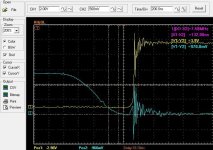
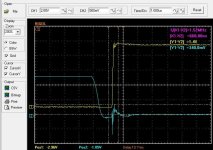
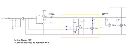
Here is what I found under load my dead time was to short.... Well kind of. I found I'm still getting the low gate pulling up when the hi side turns on. I upped the dead time and it was a lot better but the fix is a different fet driver or some more fancy work with resistors.

Here is what I think. If I turn the high side on slower then the low gate will not have as hard of an issue staying off. If I set up the low side to turn off with less resistance it should hold it off better. So between working with these two I should be able to get it sorted.
Let me know if you guys have any other tricks.
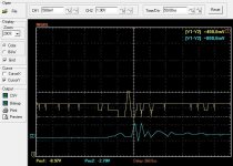
I did notice some of the overshoot as well which I think is like I had before and had to solve with caps and diodes on the rails but I will sort the gate resistors first then look at that as I up the amps. So far the over shoot is only to 105v on a 83.5v pack and the fets are rated to 150v this might be a problem as I up the voltage but I think I can spend the time setting most of it up at 84v (20s) first.

I had to quit for the day because I tried to hook a probe ground to the phase wire when the other probe was grounded to the - lol I know better but thought maybe they didn't connect the grounds in this scope... :) Apparently the ground clips form Rigol have fusible wire in them I have some more on order but for tomorrow I will try some repairs to get going. I did a self calibration and I think the scope is ok....
 

Attachments

  • 500 nS dead tim under load.JPG
    500 nS dead tim under load.JPG
    69.6 KB · Views: 1,728
  • 1000 nS dead under load.JPG
    1000 nS dead under load.JPG
    69.2 KB · Views: 1,728
Could an inclined person rig together a gate clamp by using discrete components such as a high speed opto isolator triggered off the opposite sides gate pulse + a BJT/FET to tie the gate to ground? I believe the opto is needed since the high side / low side boundary is being crossed (and we don't want to mix ground potentials) and it was the first thing that popped into my head. I'm by no means an analog wizard so I could be way off here.

High side gate drive goes high = low side gate clamp shorted to ground
High side gate drive goes low = low side gate clamp released
Low side gate drive goes high = high side gate clamp shorted to ground
Low side gate drive goes low = high side gate clamp released

Would adding an external circuit like this cause any major side effects on the gate drive? I don't believe it would increase the gate drive loop area at all since the trigger is done on the logic side.

Obviously a better gate driver with this feature built in is a cleaner solution, but something like this could prevent an entire redesign/rebuild of Arlo1's boards if an add on external daughter boards would be doable.

Amateur hour is over, time for the pros to weigh in.
 
OK small update its different on all three days phases. Phase b has only about 500ns from the time the low gate starts to move off till the low drain goes up the other two are 1us which is what I programmed. Phase C last looks ok.... It has 17v 1/8w zeners on drain to source and the other two are 15v zeners I wanted to try this to see which one would be better. This is a good test for my diagnostic skills. :)
 
Up date I figured out what b phase was is when it was shutting off the low side the drain was going high because of the other side of the motor and as I type this I realize when it does that the gates are ok which means the problem I am having in the low gate is caused by something in the fet driver or the caps for the buffer FETs..... Hmmmm.
 
that "miller effect" turn on when it should be off.. has nothing to do with deadtime. if you increased deadtime and found an improvement it is because you had some other problem that was solved by this action. during development test it is better to have longer deadtime and shrink it down rather than other way around.

If I turn the high side on slower then the low gate will not have as hard of an issue staying off. If I set up the low side to turn off with less resistance it should hold it off better. So between working with these two I should be able to get it sorted..
^Yes! now i see you understand the situation perfectly

Let me know if you guys have any other tricks
actually there is a lot you can do but you asking a solution for a gate driver that already exists, and that will limit your options. how much hacking do you want to do?
 
zombiess:
Could an inclined person rig together a gate clamp by using discrete components
yes you can implement an active clamp by discrete components. when the PWM_OFF signal is delivered to gate drive IC, needs time to permit normal turn OFF through the gate resistors and then pull gate to source through a mosfet. when PWM_ON is issued the clamp has to automatically disable.

think about it, post a concept schematic. test it in simulation if you can
 
Ok I scoped the thing all day changing resistors around and I then went back to the shop to see if the driver was sending a signal for this to happen and its not but the signal to the buffer FETs is at zero from the driver but they get the spike probably causing them to turn on when they should be off so.....
Simple fix??? Pull down resistor on the gate to the buffer FETs??? Maybe if I don't fall a sleep after my salmon I will run to the shop to try. Wonder what value I should try.?
 
OK now I have my work cut out for me. I have tried a lot of stuff. But the problem is not realy in the driver or the buffer fets.

Highhopes would this miller effect happen with isolated supplies for the high side?

As a fix circuit would a guy not just be able to put a transistor from gate to source on the low side fets and hook its gate to the high side signal from the fet driver?
 
Lebowski said:
First thing to measure is the voltages to the motor to see if you have ringing there (this is also supply dependent).

The turn on your talking about concerns a current induced in the drain to gate of the FET. This current then goes into
your gate driver (including its series resistor). If the gate drive resistor is too large the current times the resistor
gives a voltage that keeps the FET on. The effect should be very short but will give some sort of shootthrough. The
bigger the FET (current rating), the worse this effect as the drain/gate current will be bigger. This is why I don't
like 'logic level' FETs, the have a 4V turn on voltage instead of the (easier to keep off) 8V for standard FETs

If you keep popping FETs, are you also popping gate drivers ? If you have a bootstrap type supply for the gate
driver the supply voltage can be too high on the high side. When the low side FET turns on the motor terminal
(which is the negative supply for the gate driver high side) will go a bit below 0 V (due to ringing, inductance etc).
The supply on the high side gate driver is then the 15V supply plus whatever amount the motor terminal goes
negative. I solved this by putting a small resistor in series with the bootstrap diode, this makes the bootstrap
supply circuit too slow to follow the negative overshoot....
Might need to try this... And its good to understand that now its worse because I have 4 fets in parallel rather then 3....
 
A 10 ohm resistor in series with the bootstrap diodes didn't seam to help.


Now... I realized this problem with the false trigger is not there when I use PWM test mode which means it must be caused when current flows though the rails... Maybe I need to add more caps to the rails.?
 
Going back through my notes. The last time I had this problem was when the low turned on the hi side would get the miller effect on the gate right now the problem is on the low side gates and I can see a spike in the rails and everywhere on the system which means to me its caps now the question is what capacity do I add....? I think what is happening is the ground rail gets pulled up a bit as the hi turns on under load then the it springs back and this is when the gates on the low get the miller effect. So... More caps will be good but something that holds the gates to ground will be the true fix I think. I also think I can just use the hi output from the ir2113 to do and while I'm at it I can do both hi and low!
Maybe this will be a good step in making this thing bullet proof!
 
Now I see the benefit of isolated supplies to the fet driver circuit. If I try to simply add a trasnsitor to hold the low fet off when the hi is on it risks switching when the ground shifts around.... Hmmmm.
 
Arlo1 said:
Going back through my notes. The last time I had this problem was when the low turned on the hi side would get the miller effect on the gate right now the problem is on the low side gates and I can see a spike in the rails and everywhere on the system which means to me its caps now the question is what capacity do I add....? (...)
I'm not seeing the exact situation but the positive rail spike can be due to parasitic inductance from the top FET drain into the "real" caps. Needs good low inductance cap rail-to-rail "on top of" the FETs.
 
sometimes you have to learn the hard way..

Highhopes would this miller effect happen with isolated supplies for the high side?
yes. the miller effect has naught to do with power supply. read Lewbowski's message to you first paragraph as it is explained there better than i did. his second paragraph about bootstrap supply i can not comment as i have never used that type of power supply, being that it is very inferior and in my opinion only good for 1kW drives.

As a fix circuit would a guy not just be able to put a transistor from gate to source on the low side fets and hook its gate to the high side signal from the fet driver?
technically speaking, a girl could do this too. :wink: but implementing in the exact way you describe may solve the miller effect but it will introduce a new problem which is turn OFF too fast.

what you really need is to keep the turn OFF resistors as they are.. then after the mosfet is OFF engage the clamp.

by the way, i used PSpice to model your mosfet and found that each one has 60mA current injected into gate resistors PER MOSFET. that is from the junction capacitance itself, at the die level. with 5 ohm gate drive resistor that would be 1.2V miller effect which is no problem. at 10 ohms it probably acceptable. any turn OFF gate resistor greater than 10ohm equivalent will be too high for your current design (assuming PSice is 100% accurate).

the SOT-227 package mosfet i am using in my inverter is actually worse in this regard than your 4 parallel mosfets. but i knew this problem going in so already decided to use a gate driver chip with clamp function (or else i would have used -5V negative bias turn OFF power supply).
 
OK so as a girl.... The low side is comanding the FETs off first then the hi side commands the other FETs on so..... by using the signal from the opposite side in this case the signal from the hi side to hold the clamps on the low side gates it should work because the FETs should be already off!
 
something like that could work but would be harder to implement and cost more than is apparent because you are asking for low/high side to communicate to each other but they each have very different reference ("ground").

what about this idea..
gate driver receives PWM_OFF command. gate drive IC pulls mosfet low through Rg_OFF in normal way. once gate voltage is sensed to be below threshold voltage (say 2Volts) then a comparator chip is triggered which tells a small low current N-channel mosfet to short-circuit the main power mosfet gate to source. then, later gate driver receives PWM_ON command... but be careful here beacues the small N-channel mosfet is still shorting the power mosfet gate pin, so this PWM_ON command has to somehow tell the comparator that the voltage sense is now high and output of comparator chip goes to opposite rail thus informing small N-channel mosfet to STOP conducting.
 
HighHopes said:
something like that could work but would be harder to implement and cost more than is apparent because you are asking for low/high side to communicate to each other but they each have very different reference ("ground").

what about this idea..
gate driver receives PWM_OFF command. gate drive IC pulls mosfet low through Rg_OFF in normal way. once gate voltage is sensed to be below threshold voltage (say 2Volts) then a comparator chip is triggered which tells a small low current N-channel mosfet to short-circuit the main power mosfet gate to source. then, later gate driver receives PWM_ON command... but be careful here beacues the small N-channel mosfet is still shorting the power mosfet gate pin, so this PWM_ON command has to somehow tell the comparator that the voltage sense is now high and output of comparator chip goes to opposite rail thus informing small N-channel mosfet to STOP conducting.
I for got about the reference of the ground for the Hi side... But I could use the input side of the ir2113 to feed to a fet driver.

As for your suggestion its probably not hard I just want to take the time to get something together that wont take up a lot of space.

First think I will do though is try adding some more cap to the traces. I don't have anything over 220uf on there yet. I have a bunch of expensive screw terminal caps to put on the bus bars. I designed this with putting some of them on the copper in mind.
 
i tried to simulate it it on its own and active clamp was functioning, then i put it in my inverter circuit to simulate under more realistic conditions and it kept crashing. i'm too tired now to keep working on it.. so i just post the picture here as an unproven concept for discussion only:
 

Attachments

  • Active_Clamp_R0.jpg
    Active_Clamp_R0.jpg
    39.5 KB · Views: 683
Thanks for your hard work man.

Here is a scope shot saved to my computer it shows what I'm talking about on the rails. I will have to try to remember if this was normal but I think this is more then before. But now that I had this problem I will really think of ways to hold the gates off when they really need to be.

It shows the rail ringing with it going down then up then the next time down is fast enough for the gate to get a signal about the same voltage which in this case is 4v.

This is where some electronics engineering would be handy because I love being creative but I don't know all the ways I can make this work.

Yellow is rail voltage blue is gate on the low side. This is happening when the hi is turning on under load.
 

Attachments

  • Rail 4v drop.JPG
    Rail 4v drop.JPG
    63 KB · Views: 1,582
If you want to hold the MOSFETs off, I think a good way is to drive the gate negative when off. So you have like +15V/-5V, +10/-10 or similar. The negative voltage will add to the gate treshold. It requires a more complex gate driver, and an extra voltage on the board, though. And on some MOSFETs, their voltage rating will decrease if you put the gate at a negative potential. Have never tried this in practice, but simulations looks good.

I also think the ferrite bead is a good. Again, I have never tried it in practice. But the results of the simulations looked good when I found the right ferrite bead.
 
You don't want to float isolated DC/DC's tied locally to source for reference for high-side gate drive supply?
 
liveforphysics said:
You don't want to float isolated DC/DC's tied locally to source for reference for high-side gate drive supply?

I have gone to boot strap for the last while because of price. When you start paralleling lots of FETs you need some decent isolated power supplies and I could not find a very good selection at a reasonable price. I will consider this again as well.
BUT adding a isolated supply to the hi side is not going to solve this problem. I believe the problem is when the ground floats around its puts a small charge into the low gates.
 
If you tie an isolated DC/DC to float in reference to source voltage, I think it won't matter how much grounds jump around, as the increases/decreases in local voltage at the source's bounces will be tracked by the floating supply.

If I buy you 6 of these and have them shipped to you, I have a hunch it will solve these problems.

http://www.ebay.com/itm/DC-Converter-Isolated-Power-Supply-In18V-75V-Out-12V-6W-/350287013003?pt=LH_DefaultDomain_0&hash=item518ebba48b
 
liveforphysics said:
If you tie an isolated DC/DC to float in reference to source voltage, I think it won't matter how much grounds jump around, as the increases/decreases in local voltage at the source's bounces will be tracked by the floating supply.

If I buy you 6 of these and have them shipped to you, I have a hunch it will solve these problems.

http://www.ebay.com/itm/DC-Converter-Isolated-Power-Supply-In18V-75V-Out-12V-6W-/350287013003?pt=LH_DefaultDomain_0&hash=item518ebba48b
I will see what I can find tonight the ones you posted need 18-75v input and my pack is 84 ATM but I'm heading for 28s! So either 12v in or 50-140v (or something close) in! 6 watts..... when I plan to push current to 8 ixfk230n20t in parallel might be pushing it as I up the PWM frequency!

Edit..... Wait I don't think that will solve this problem... because the trigger is Gate over source and source is tied to buss bar (-) on the irfp4568 so when the (-) buss bar bounces around it triggers the gate. The capacity in the fets and the inductance and resistance in the traces causes the gate to not stay tied to buss bar (-) though all of the traces and components involved so I think the 2 things I need are 1 something to tie the gate right to ground after its off but before the hi side turns on and 2 more caps on the buss bar.
 
Arlo1 said:
Yellow is rail voltage blue is gate on the low side. This is happening when the hi is turning on under load.
To me it looks like you need better decoupling at the rails to start with, "on top" of the FETs (you know, film cap low inductance small value etc). When the FET starts pulling the current, you have a deep on the rail, caused by the parasitic inductance from the *real* caps (= ignoring caps own parasitics) to the FET. You know, you try to pull a lot of current suddenly and the parasitic inductance doesn't like that, so it "lowers" the rail voltage to slow down the current rise. If you do the exact same measure but at the caps legs you'll probably have a smaller deep (assuming you measured the yellow trace at the FETs legs; if you measured it at the caps, then you should have a bigger deep at the FETs legs [drain]). That is, if that rail ripple worries you. Just my opinion!
 
Back
Top