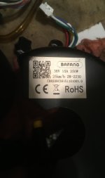
Do you have a link? Why did you choose a CAN bus model that you can't communicate with?
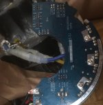
There' are lot's of resistors or other smd's around LCD connector- so maybe it was tosted first...
The sequence of events probably went like this.
The
excessive voltage supplied to the throttle's hall sensors integrated circuit made it break down and short to ground.
This created
excessive current in the ignition circuit that is enabled thru the display's transistor "ON" circuit that's activated by the "On" button. Thereby causing it to fail and in this instance short in the closed position keeping it "ON" at all times.
The hall sensor was painfully obvious.
The display when
opened for inspection will probably reveal similar electronic damage and distress.
Which brings up an important thing to look for... A typical wiring harness is capable of handling a current of 2 amps per wire.
More for a short length of time. As we don't know for sure how many amps were passed and for how long, it would be wise to verify the integrity of each of the individual wires in the harness.
This would be done by checking the resistance of each wire, having
one end not connected to anything.
With one probe at the PCB board, and the other at the appropriate pin designation. Verify full continuity between them. And also importantly, check from the same PCB landing or position to all the other pins to make sure they are not shorted together.
Note that some controller points go to more than one pin on purpose, also verity all is well.
Naturally, you could also purchase a new harness... But the controller's wiring would still be suspect and need to be checked.