Balancing 4S4P pack

Rollodo

1 kW
Joined
Sep 25, 2011
Messages
408
Location
Brooklyn, NY
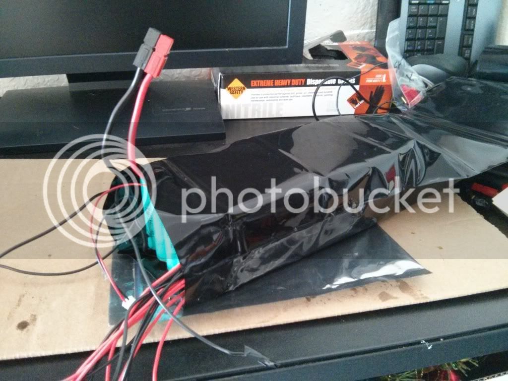
I posted this question in the 20R/24R cell thread, but after thinking about it, I decided that it wouldn't be the best place for it. The question is this: I've got 4 new Panasonic 24R cells in 4P bricks; does the following diagram conform to the balancing standards? I've never built my own packs, let alone balanced one.

I have another 12 4P bricks coming in the next couple of weeks, for the purpose of building a 16S 4P pack.
 

Attachments

  • Balancing 4S4P v2.jpg
    Balancing 4S4P v2.jpg
    53.7 KB · Views: 3,220
Not even close. Play with this.
http://scriptasylum.com/rc_speed/lipo.html
 
Assuming the 4 groups of on the right are the bottoms of the cells on the left pack
ie the ones on the right are the left cells flipped top to bottom around the horizontal axis then it looks like it might be correct.
 
but still there are some connections missing. and the balance leads are crossing. why should that be?
make a string by connecting cells from left to right from plus to minus oder minus to plus. connect a balance lead at every connection and that's it. that's really no rocket science and can easily be found by typing "lipo balance wiring" and google pictures.
edit: ok. those connections MAY be on the bottom of the batteries, but as long as someone can't see them we can't say if it's right or not. and still the connection between the left and right picture is missing.
 
wesnewell said:
Not even close. Play with this.
http://scriptasylum.com/rc_speed/lipo.html
I did - this is still what I came up with.
izeman said:
I'll give you a small hint: some of those batteries are not even connected. How would energy be able to flow through the pack?
They are indeed connected - the whole this gives me 14.56V, check this (in that thread):

file.php

Ricky_nz said:
Assuming the 4 groups of on the right are the bottoms of the cells on the left pack
ie the ones on the right are the left cells flipped top to bottom around the horizontal axis then it looks like it might be correct.
Correct - in the original post I indicated that I only have 4 4P bricks, meaning that what we're looking at are two sides of 4 4P bricks, not 8 4P bricks.
 
there is an easy way to solve this: IF this battery is an 8s pack - giving you something around 20-30v from minus to plus, then you just have to find connect the red lipo balance wire to the outer most plus. then take your voltmeter, measure the voltage between this plus and the connection. it should add the voltage of one cell per connection. so if you've found the connection that measures around 3.5v you got your first black balance wire (next to the red one). then look for the one with ~7v and connect it to the second black wire. and so on, until the last black wire goes to the outer most minus of the pack, and you have full pack's voltage across those 2 wires.
hope this helps
 
izeman said:
there is an easy way to solve this: IF this battery is an 8s pack - giving you something around 20-30v from minus to plus, then you just have to find connect the red lipo balance wire to the outer most plus. then take your voltmeter, measure the voltage between this plus and the connection. it should add the voltage of one cell per connection. so if you've found the connection that measures around 3.5v you got your first black balance wire (next to the red one). then look for the one with ~7v and connect it to the second black wire. and so on, until the last black wire goes to the outer most minus of the pack, and you have full pack's voltage across those 2 wires.
hope this helps
I'll apply this concept and check the pack's voltage at each series state, but this pack is 4S, not 8S.
 
I'm seeing two separate 4 s packs in the pic. So yeah, not even close. Looking at just one of them, half your balance wires will need to be connected to the other, not shown side of the pack. One the negatives on that side, since every other row is facing the other way to make the serial connections.

Cell wire number one, is the main - for the whole pack. 2, 3 and 4 are all connected to the negatives of each set of 4p batteries. Again, half those negatives are on the other end of the pack. The last wire, #5 or just + is the other end of the whole pack, the red positive wire.

You can take each of those 4p packs, and parallel them at the main wires, and if you wish, you can also parallel the balance wires to connect the two packs in parallel at the cell level, allowing you to balance charge both simultaneously.
 
dogman said:
I'm seeing two separate 4 s packs in the pic. So yeah, not even close. Looking at just one of them, half your balance wires will need to be connected to the other, not shown side of the pack. One the negatives on that side, since every other row is facing the other way to make the serial connections.

Cell wire number one, is the main - for the whole pack. 2, 3 and 4 are all connected to the negatives of each set of 4p batteries. Again, half those negatives are on the other end of the pack. The last wire, #5 or just + is the other end of the whole pack, the red positive wire.

You can take each of those 4p packs, and parallel them at the main wires, and if you wish, you can also parallel the balance wires to connect the two packs in parallel at the cell level, allowing you to balance charge both simultaneously.
Guys, once again, thanks for your input; however, I've already stated in 3 places (the thread title, original post as well as last post) that it's just one 4S pack. I believe the proof lies in the the picture with the multimeter showing correct voltage for 4S. Due to limitations of both my budget and technology, I cannot take one picture of both sides of the pack (can anyone?). There is a total of only 16 cells in the pack - 4 bricks of 4P. Please look at it as one 4S4P pack; otherwise, I am getting confusing myself thinking that what I've connected together is a 4S4P pack, whereas in actuality I'm a total loser and cannot even add things together.
 
if the right side of the picture is the lower side of the pack, then imho is wired correctly as a 4s4p pack.
why don't you just do it and measure the voltages at the balance plug to see if from one pin to the next voltage adds up until it's the full pack's voltage between pin1 and pin5? what can go wrong as long as you don't connect the connector into anything?
 
Sometimes a picture just confuses things. That's what yours did by looking like 8 cell groups when you combined the top and bottom into one photo. Balance wiring is about as simple as it gets as indicated in the link I provided. In text terms it's simply the first wire to the positive side of the cells in series and then next wires to every negative terminal thereafter. For a 4s pack that would be 5 wires. For a 24s pack, that would be 25 wires.
 
The first pic is a bit confusing but yes the sense wires are where they should be.
An easy way to think of where the sense / balance wires should be placed is to start with pack negative as where sense wire zero will connect.
Then the next wire will go to the positive terminal of cell ( bank ) 1.
The next sense wire will go to the pos of cell 2 and so on till you have 5 wires for the 4 cells.

Have fun
 
izeman said:
yes. it should work. but as stated earlier: just solder the wires from the balance plug to the battery and measure at the plug. that's it.
I will. Everything I did here (including the N42 magnets) was just to verify that the setup will work as intended. Now that I know this will work, I can solder things together.
Icewrench said:
The first pic is a bit confusing but yes the sense wires are where they should be.
An easy way to think of where the sense / balance wires should be placed is to start with pack negative as where sense wire zero will connect.
Then the next wire will go to the positive terminal of cell ( bank ) 1.
The next sense wire will go to the pos of cell 2 and so on till you have 5 wires for the 4 cells.

Have fun
Yep, noted. Thanks for your input.
 
Yep the pic blew my mind, and I read the text too fast. I was sure I was looking at two packs, so then just try to convince me what I saw was wrong. :roll:

My apologies for that. Looking at the pic now, I don't think you have the wires in the right order. You can't have two positive terminals at the end of the string is what I mean. I may be still confused as hell, but I think if you flipped one of those pics over, then drew the lines in the same places, then it would be correct. You have one end that is the main -, and another end is the main +. Your pic shows both ends have a +?

Again, trying to just explain the correct wiring order, regardless of what any picture shows or how confused it got me,

Wire 1 is the end negative. 2,3,4 keep attaching to the negative. 5 is the last wire, on the positive, the only positive on the end the pack has.
 
Whwew! Ok, looking again, again, I think I now get it what the pic shows. It is correct. I'm just getting thrown a bit by not quite understanding which terminals on the pack are the main discharge points. Made me think it was two positives and no negative.

Gone to look one more time,
 
Ok, yes, your original diagram looks correct. On the left pic, the far left and the far right cell groups are the main discharge points. At first glance, I was thinking the main negative would have been on the left picture. It would be with 3, 5, 7 cells etc, but not with 4 cells as you have.
 
After I solder the balancing and main leads, would it be okay to tape it all together with an electrical tape? The reason I ask is because I want to make sure that the discharging current won't heat things up to a point of melting stuff.

EDIT: I might need some major heat shrink sleeve (no idea where to find one at the moment), like migueralliart did here - http://endless-sphere.com/forums/viewtopic.php?f=14&t=48074&start=75#p718270

IMG_20130324_155528_zps0a70ed8d.jpg


No quote, just calling out - do you mind sharing where you got that sleeve?
 
i made good experience with this buyer: http://stores.ebay.com.hk/FIND-HIFI/PVC-Heat-Shrink-Tubing-/_i.html?_fsub=4428142016&_sid=1117136446&_trksid=p4634.c0.m322
order some pvc heatshrink that is some mm wider than the pack you want to cover. the dimensions given are a bit unclear - or at least confused me. there are two dimensions: flat and diameter. if you multiply the flat value by two you get the circumference =2h+2l (where h,l is the height and length).
 
Might be a good idea to use some tape too. Or some more heatshrink for the balance wires. What I mean is, something between the sense wires and the metal tabs, unless you use very tough wire. So you don't have a bit of vibration on the road sawing the strips into the wires and shorting it.

Grin used to stock large heat shrink. There is also the coke bottle trick. If the right size, you can cut a large coke bottle into a sleeve and then shrink it on a pack.
 
I looked around and it seems that this kind is what I need: 3ft = 36" = ~92cm = pretty long, as my pack will be roughly 4 * 100mm each 4S4P brick = 400mm = 40cm. I also don't plan to wrap the whole thing, but wrap each of the 4 bricks separately.

IMG_20131210_124324.jpg


According to the photo above, if the circumference (C=D*Pi) I need the tubing to be is about 28mm (to be on the safe side), the diameter of the tubing should be:

28 = x * Pi
x = 28/3.14 = 8.917 cm ~ 90 mm = 3.54". Does this look legit?

Or this one - 80 pieces of 4" x 10". Cut one in half and I can wrap two bricks.
 
Back
Top