Battery Backpack and Retracting Power Lead Project

Here's some ideas for cord management...

Metal_Badge_Holder.jpg


USB-executive-mini-computer-mo-5130115.jpg


092310_tf_phonecordduh.jpg


And when you finally feel your build is accomplished and ready for duplication, let us know. I'm sure some of us here would buy one :!:
 
How do you find the weight of the packs? I've got a 12S2P setup on the handlebars and find it a tad too heavy to hoik the front up over logs.

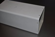
In the hardware stores we have stuff like this for downpipes (ie roofing guttering) in PVC - 50X100 and 65X100. Nice rounded corners, and the endcaps I use are simply offcuts I run lengthways through the saw table to make 'U' shaped pieces, which then get glued with PVC cement. Might make up a test setup and see how livable it is. Rounded corners on everything make for a bit more comfort and also less likely to wear through fabric.

I've got an ALDI hydration backpack that usually gets used for important errands like picking up wine and longnecks from the bottlo - Might be a more sensible use for it. (well, it is still being used for hydration). :mrgreen:

Oh for those not familiar - bottlo - bottle shop, longneck 750ml(?) - beer.
 
heathyoung said:
How do you find the weight of the packs? I've got a 12S2P setup on the handlebars and find it a tad too heavy to hoik the front up over logs.

In the hardware stores we have stuff like this for downpipes (ie roofing guttering) in PVC - 50X100 and 65X100. Nice rounded corners, and the endcaps I use are simply offcuts I run lengthways through the saw table to make 'U' shaped pieces, which then get glued with PVC cement. Might make up a test setup and see how livable it is. Rounded corners on everything make for a bit more comfort and also less likely to wear through fabric.

I've got an ALDI hydration backpack that usually gets used for important errands like picking up wine and longnecks from the bottlo - Might be a more sensible use for it. (well, it is still being used for hydration). :mrgreen:

Oh for those not familiar - bottlo - bottle shop, longneck 750ml(?) - beer.

Excellent use of a hydration pack!

I've run a similar set-up on the handlebars and never liked it (see the kona build in my signature), but I don't really notice 12'ish pounds on the back (but, I ran for several months with 3 12ah SLA's in a backpack set-up when I first got into e-bikes :p) . The real trick is making the power lead feel invisible and still quickly disconnect with unfortunate bicycle-pilot separations 8)
 
Yeah those separations happen a bit too frequently to me these days :)
 
I've been back to the drawing board and redesigned these packs as 10s1p holders, this makes each tube approx 9" in total length. I've got enough batteries to make 3 tubes as it sits.

I've also changed the Anderson mounting system to a much simpler design- the Andersons slide in snugly and then are held in place with a single screw, much more secure and far less fiddly than my previous design.

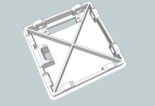
Here's the top in it's current form:
Power Tube Top 021913.jpg

I've added an Anderson mount to the bottom tube cover to use as a quick-connector I plan to add to the bottom of the backpack mounts in the future. I hope to just slide it in like a tool pack battery and go.
View attachment 5

I've also redesigned all the backpack mounts to use 2" wide 1/8" aluminum strips since these are easier for me to find at the local big box hardware stores. Here's the bottom with a cutout that will eventually hold the bottom battery quick connector assembly.
View attachment 9

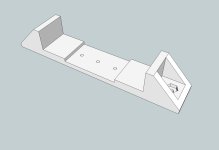
And the mid mounts, just changed the aluminum size on these.
BBP Mid Mount Single.jpg

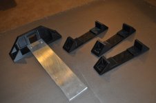
All the parts printed, with the aluminum ready to assemble. I've also moved toward using these 2" cinching velcro straps that I've used on previous builds, they snug nicely and hold very secure.
BBP Single parts.JPG

This shows the quick-connect cutout a little better.
BBP Bottom cutout.JPG

All printed parts riveted to the aluminum, ready to be mounted on backpack of choice.
View attachment 3

And with the tube in the mount, all velcro'd in.
velcro 1.JPG
velcro 2.JPG

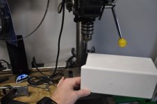
I started battery tube assembly, drilling holes with the template I printed earlier- works as designed.
drilling tube.JPG

After I drilled 'em all, you can see the holes don't leave a whole lot of material between the top of the hole and the end of the tube. I'm going to use these as is, but I'll changed the design if this becomes a failure point.
tube holes.JPG

I also designed a cell-log holder, but I haven't printed this out yet.
Power Tube Cell Log Mount 021913.jpg
 
file.php


More velcro please. Just doesn't look secure enough. :eek:

I think the most important part of the pack is the lumbar strap. If you're able to dial in your pack weight and keep it low (lumbar region), you get a great deal of comfort and maneuverability. Some sternum straps probably would help comfort as well and get that nice compact "feel" too. I used to play around a bit on a baritone saxophone. Lugging the instrument case was a huge chore, so I made a harness and built 2x arm straps and a lumbar strap from web belts purchased from REI. The lumbar strap was the key to comfort.
 
melodious said:
More velcro please. Just doesn't look secure enough. :eek:

Of all the (numerous!) points of potential failure, the velcro is the least of my worries- it's very secure.
 
On to the double tube mount. These are designed to be mounted inside a standard backpack, very stealthy and I don't have to worry about the batteries jumbling about and/or crash damage.

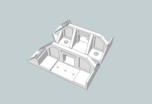
In order to print on my 200mm bed (190mm actually usable), I split each of the mid mounts and the bottom mounts in half. A healthy dose of ABS cement should make for a solid one piece unit- the flat end joints will be fused together for final assembly.

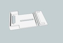
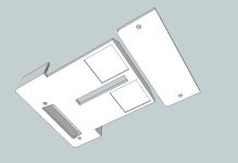
Here's the mid mount sketch up file:
View attachment 2

And the bottom ( this was a 7 hour print):
BBP Bottom Mount Double 022213.jpg

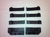
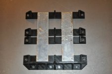
All the printed parts of the double battery tube mount, ready to be bonded together:
BBP double printed parts.jpg

Once the printed pieces are fused, the final assembly will look like a side-by-side version of the single mount.

Made a little progress on the cell-log mount as well. This part plugs in to the DB-25 connector on the top of the battery tube and looks pretty good.

Just need to solder in the connectors:
View attachment 1

Add a couple screws and it's buttoned up:
cell log with cover.jpg
 
Nice. Every time I see a 3D printed part it brings me closer to pulling the trigger on buying one!

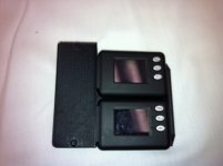
Seeing as you can print essentially anything, why not remove the face from the cell logs and print a new cover to surround the 2 with just a cut out for the screen (+/- the buttons if you dont use them)
 
Hyena said:
Nice. Every time I see a 3D printed part it brings me closer to pulling the trigger on buying one!

Seeing as you can print essentially anything, why not remove the face from the cell logs and print a new cover to surround the 2 with just a cut out for the screen (+/- the buttons if you dont use them)

go one step further... wire each celllog's buttons up to a spdt switch - so you can controll all of 'em with just one button!
 
Hyena said:
Nice. Every time I see a 3D printed part it brings me closer to pulling the trigger on buying one!

A guy like you, with all those builds- you could definitely make use of one (or two!).

Hyena said:
Seeing as you can print essentially anything, why not remove the face from the cell logs and print a new cover to surround the 2 with just a cut out for the screen (+/- the buttons if you dont use them)

I pulled the case off of one of these and promptly put it back on! I'm not there, design skill wise, to pull it off yet. But maybe someday.
 
if you leave the cellogs attached they will draw current only from the lowest 2 cells and create some imbalance in the pack charge. fechter has a hack for the cellogs to take power from the top cell in the group and heath also has a pcb designed to do the same thing.

did you make the velcro straps or buy them?
 
Hyena said:
Nice. Every time I see a 3D printed part it brings me closer to pulling the trigger on buying one!

Seeing as you can print essentially anything, why not remove the face from the cell logs and print a new cover to surround the 2 with just a cut out for the screen (+/- the buttons if you dont use them)

there's even some which you can charge the polyamid with Al and you get a piece with 30% less stress resistance than conventional Al...
 
dnmun said:
if you leave the cellogs attached they will draw current only from the lowest 2 cells and create some imbalance in the pack charge. fechter has a hack for the cellogs to take power from the top cell in the group and heath also has a pcb designed to do the same thing.

Ya, I've been running cell-logs for nearly two years and just unplug if my pack will be sitting long

dnmun said:
did you make the velcro straps or buy them?

Bought 'em from the big hardware store in the sky: http://www.mcmaster.com/#hook-and-loop-cinching-straps/=lnhci4
 
Here's the double pack holder all bonded together. I've mounted it into a backpack already, but no pics of that yet.
BBP double bonded together.JPG

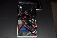
A look inside the top of the battery tube showing the room for wires and connections. The packs have foam padding surrounding them on the other sides and a piece (not shown) goes on the top. The packs fit into the PVC tube very snugly, there is zero movement with the padding.
inside top power tube.JPG

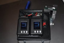
A couple shots of the cell log mount (there's a cover that goes over the exposed DB25 connector, just not installed). This is the older style, but he newer version looks very similar. See below.
open cell logs top.JPG
open cell logs top and side.JPG

With the previous version of the cell log mount, there was too much space between the mount and the top of the battery tube and the DB25 connector wasn't fully seating. I changed it up to bring the cell log mount almost flush against the top of the battery tube and added a couple recesses for 3/4" square velcro to hold the bottom half secure. I've printed these, but haven't installed 'em yet- here's the drawings:
Power Tube Cell Log Mount 030313 bottom.jpg
Power Tube Cell Log Mount 030313 top.jpg
Power Tube Top 030313.jpg

I've been doing a bit of playing with the power lead and how best to implement a retractable cord. I've made some progress with a tube version that utilizes a a bungee cord and pulley mechanism, but it is not as "invisible" to the rider in all positions as I'd like it to be so I'm probably going to go in another direction. I'll get some pics of my current version up in the next couple of days.

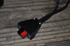
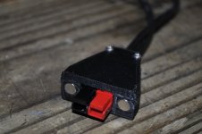
One element of the current design that is working very well is the Anderson connector housing with integrated magnets. Here's the drawing:
View attachment 12

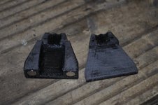
Printed with a bit sanding prior to installing connectors and bonding the two halves.
mag connector raw.JPG

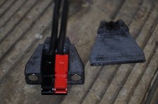
With the connectors in.
mag connector with andersons.JPG

Clamped while the ABS cement works it's magic.View attachment 7

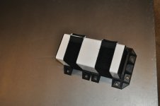
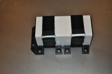
And a couple shots of the fully assembled male-side housing. I don't have pics of the female side, but the Andersons just sit flush with the housing, rather than extending out.
mag connect assembled top.JPG
mag connect assembled front.JPG

The two screws in the back clamp down on the wires and act as a stain relief. The housing itself is bonded to the connectors, but the wires can still be removed/changed. The magnets are oriented so that the connector will only align and connect in one way. It's pretty easy to connect this lead with only one hand and the magnets add a good bit of strength to the connection while still allowing for relatively easy disconnect.
 
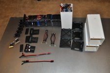
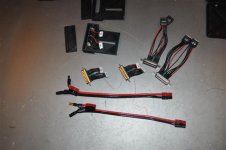
Finally got some time to get all the soldering done on the battery tubes. The DB25 connectors are pure tedium to connect, put it off too long. Here's the work table after all the soldering was done this afternoon.
DSC_0085.JPG

A little tighter shot on the actual PITA connectors.
DSC_0089.JPG

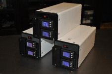
Fast-forward a couple hours and here are the good little stomtroopers lined up for inspection.
View attachment 3

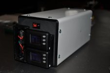
With the cell-logs mounted:
DSC_0096.JPG

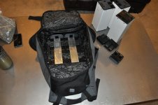
A shot of the backpack I'm using with the double battery pack mount inside.
DSC_0100.JPG

And with the tubes buckled in nice and snug.
DSC_0104.JPG

At this point I'm happy with the battery tubes and will plod along with the current design until I find a fatal flaw are something fails and requires a re-do. I was surfing hobby king the other day and found these: http://hobbyking.com/hobbyking/store/__18209__Turnigy_nano_tech_8000mAh_5S_25_50C_Lipo_Pack.html . These are Turnigy nano's in 5 series, 8000 mah bricks that measure just 194x45x47mm. If I cut these tubes just a bit longer (maybe make 'em 11 inches rather than the current 9 inches), I should be able to fit four of these in a tube. That would double my current set-up's capacity and increase size of the tube just 2 inches. I'll look into these for my next battery purchase.
 
Keen observers will notice I've changed the title of this thread to incorporate my trials and tribulations on my journey towards building the ultimate power lead solution. Ideally (to me), the power lead should easily connect to the bike, disconnect in a crash relatively easily and be just about invisible during all other aspects of riding.

So far, I'm very happy with the magnetic Anderson connector housing I posted pics of earlier in this thread. This connector covers the first two requirements. The third requirement, however, is where the challenge really lies. I've got a few ideas about how to accomplish this, this next post will cover attempt number one.

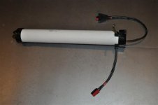
Here's all the parts of the mechanism laid out. Essentially, there is a pulley on the end of a bungee that feeds/retracts the power cord into/out of a PVC tube. In its resting state, the bungee holds the pulley with the power cord at the top of the PVC tube. As the rider moves around on the seat, stands up, what-have-you, the bungee is put under tension and the power lead is doled out.
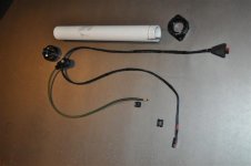
DSC_0109.JPG

A closer look at the power lead carrier pulley. There are two sealed bearings inside the printed pulley and it rolls very smooth.
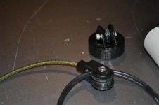
DSC_0111.JPG

There were multiple iterations of this pulley carrier:
View attachment 8

There is another pulley at the top of the tube. This is where the bungee cord runs.
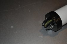
DSC_0117.JPG

All put together.
DSC_0115.JPG

This the best pic I could get before I just gave up on it, but it shows the power lead pulley carrier in the fully extended position at the bottom of the tube. If you look closely, you can see have the pulley actually guides itself along the inside run of the power lead and keeps itself aligned. This happened by accident, but it works beautifully.
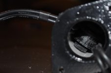
DSC_0125.JPG

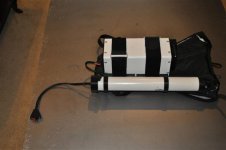
This is the old single battery tube test pack, looks more and more like Hyena's ghost-buster backpack :)
DSC_0107.JPG

Inside a regular back pack and you don't even know it's there.
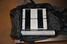
DSC_0128.JPG


But there is a problem with this design that I have not been able to solve (as of yet). The power lead extends/retracts smoothly in all rider positions EXCEPT, and this is a big one with the kind of riding I like to do, when you need to get your @ss behind the seat. Like in steep downhill descents or bunny-hopping obstacles. In this scenario, the power lead drags along the riders rear-end and this friction causes the lead to disconnect about 50% of the time. You can also feel the added resistance when it drags across your clothes even when it doesn't disconnect in this position.

So, back to the drawing board. I've got two other solutions in mind, but feel free to add your $0.02.
 
I'm liking that cord rectractor design - very clever!
 
Very nicely done, the end result looks great. Shame about the disconnection issues. Are the plugs pulling tight and yanking out or is it just a bit of tension on them that's causing the andersons to come undone ? If it's the later perhaps you could switch to a different connector type which binds more tightly. Maybe bullets or even step up to the bigger 75a andersons for your main backpack connection ? These will still come apart in the event of a crash or in routine operation but are more resistant to easily pulling out like the smaller 45a housing do. Even just the downward weight of the cord pulling on them would almost cause them to come apart.
 
Hyena said:
Very nicely done, the end result looks great. Shame about the disconnection issues. Are the plugs pulling tight and yanking out or is it just a bit of tension on them that's causing the andersons to come undone ?

Thanks man. The main problem is the power lead (silcone cables) drags on my hip/derriere-region in certain riding positions. This is an inherent flaw in having the retracting mechanism on or in the backpack itself.

Hyena said:
If it's the later perhaps you could switch to a different connector type which binds more tightly. Maybe bullets or even step up to the bigger 75a andersons for your main backpack connection ?

The anderson housings I've made up with the integrated neo-dym magnets hold with pretty signifcant force- I'm not sure I want to increase the strength of this connection as it may no longer be the "weak link" in the power cable chain. I'll probable print up a 4 magnet version to try it out though. But, no matter how strong the connectors are, it won't solve the dragging lead issue. Even if it doesn't disconnect, it's an annoyance to feel the power lead dragging on you- it doesn't satisfy the "invisible" requirement as it sits.

I'm working on variation number 2 which will look a lot like the cord organizer found on laptop mice- melodius posted a pic of one earlier (thanks melodius!):

melodious said:

Obviously, I'll be scaling it up a bit and there won't be any locking/ratcheting mechanism. This type of design should allow the lead to grow in two directions and hopefully not drag or cause significant forces on the rider. I'll post up when I've got a prototype.
 
Made some progress on the new retracting reel mechanism- there's actually a (sort of) working prototype. This is Ver 1.0 and shall be dubbed "fat man". Basically, it's a proof of concept, but it lacks in the function and aesthetic departments. I wanted to post it up here before I forget about it as I've already got a bunch of revised drawings ready for the printer.

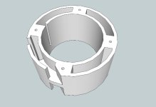
First the CAD stuff. The design centers around this 40mm ID hub which houses a standard constant force spring.
Cord Reel Hub 40mm id one piece.jpg

inside the hub is an axle about which the hub reel spins and which acts as the spring's anchor. (I must have been listening to GNR when I typo'd the pic file name 8) )
View attachment 7

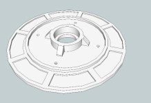
These side plates screw to the hub and hold the bearings and act as reel sides for the wire.
Cord Reel Bearing Plate 90mm od.jpg

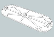
And this is a quick and dirty mounting plate to allow the whole assembly to spin- two reels go on either end of the plate.
Cord Reel Mounting Plate.jpg

I had to learn about constant force springs for this and I did that by taking apart a bunch of retracting devices- couple tape measures, dog leash, etc. The one I'm using in this prototype is from a tape measure and is too weak to retract this 12g wire without help. McMaster sells constant force spring of varying load capacity/life cycle and I've got a few ordered to play around with.

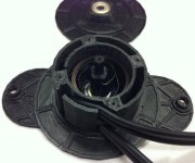
This pic shows the spring inside the hub and the routing of the wires. The hub works as designed and will transfer into the new design.
Cord Reel V1 012.jpg

This shot shows how fat the hub is- it really only needs to be wide enough for two rolls of wire. I had to oversize the hub to accommodate the inboard bearings in this design- the new version has outboard bearings (basically, I flip the side plates around).
View attachment 1

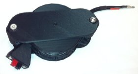
And a couple shots of the fully assembled prototype.
Cord Reel V1 004.jpg
View attachment 3

I think I'm on to something with this design and the next iteration will hopefully address the following problems:

- Spring too weak: I've got some new ones coming to test out.
- Hub/reel too fat: next version gets the bearings "outboard" of the hub. The hub will then only have to be wide enough to fit which ever is wider between the power lead wire or the spring.
- Outer mounting plate and end reels too wide: New version uses a bent style plate that tapers down to a smaller reel.

This version is using 6mm ID sealed bearings. I may change this to fit standard 608 (8mm ID skateboard bearings) as this will allow my to increase the size of the plastic axle a couple mm.

In case you were wondering about size, the hub reel outer plates are 90mm max diameter and the outer mounting plates are 140mm in length.
 
I'm guessing the cord pulls out of both ends just like the mouse cord. That would leave the whole mechanism to dangle in the middle between the rider and the bike. Would it be better to have it just pull off one end and have the reel in the pack or mounted on the bike?

I look forward to seeing version 2. What you have done so far is fantastic.

Clay
 
Back
Top