Bbs02 no voltage read by controller

rew632

10 µW
Joined
Apr 22, 2024
Messages
5
Location
Uk
Hi all I'm new here 😁

I bought a broken BBS02 750w kit with blown MOSFETs so I sorted this out and had the thing running perfectly however.. when reassembling the controller the capacitor shorted out on the metal casing... I thought not a huge deal just a cap that's discharged into the metal... Well since then my battery display is showing 0% and I'm unable to change any of the battery settings...

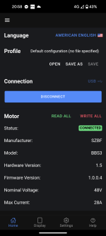
I have tested all wires running to the display and on investigation I thought I had probably damaged the display as I thought the display works out the battery voltage... Well it seems not the display gets all it's information from the controller data lines...

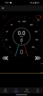
I found this out my ordering the program usb cable and hitting the display option I'm getting 0% and 0v. The really strange thing is the battery cut off voltage is at 41v yet everything works... Pedal assist and the throttle and all sensors....

So I've clearly damaged a component on the controller however I'm unsure what... Could anyone direct me in a direction of what is doing the voltage reading and transmitting this to the display?

At worst I will install a external voltage display and tag it from the controller wire but it's not ideal as it's yer more wires and bulk added to the bike.

Really appreciate any assistance on sorting this.

Thanks,

Kevin
 

Attachments

  • Screenshot_20240422-170718.png
    Screenshot_20240422-170718.png
    212.8 KB · Views: 2
Does the display change settings in the controller (assist levels, etc)?

Does any controller-supplied info show up on the display while riding?

If not, the problem is probably in the TX and/or RX to/from the display. It might be in either display or controller, or both. If there are separate chips for the TX/RX buffer(s) then replacing those will fix it. If they go direct from MCU to MCU, probably have to replace the unit (unless you can replace an MCU and have the software/firmware/etc to reflash it from scratch).

If the programming cable can talk to and read from the controller via the display connector, then the controller's TX/RX is probably fine.

Are the TX/RX pads anywhere near the cap, so that the short of the cap could have included that, feeding battery voltage to one or both?
 
Last edited:
Hey thanks for the reply, the controller is changing the PAS level and wheel speed settings. When I use the program cable it shows the settings that were changed by the display. The TX and RX seems to be working fine. I don't see anything for current detection so I'm guess that could be damaged as well?

The controller shows speed data as I cycle. With my limited knowledge on this controller I would say the issue has happened around the current shunt area as this is where I saw it spark and I'm guessing that's why I see no voltage or current.

Would anyone know how the voltage / current is measured in this controller I think its honestly some passive consonant that's been damaged and its almost £100 for a new controller :(

The odd thing is that the controller still works at 0V? I thought this would disable the drive as its under the cut off voltage of 41v? Is it possible the controller is seeing the correct voltage but however that data gets into the communication side of things its not displaying?

Thanks,

Kevin
 
If you look at the controller, there is a brown wire and an orange wire that go to the display. The brown wire is connected to the pack + and gets switched on/off by the display and sends pack voltage back on the orange wire. Somewhere between the orange wire and the MCU chip, there has to be a trace and some voltage divider resistors. You would need to trace out the circuit from the orange wire to the divider resistors. Likely the trace burnt or the resistor went open circuit.

With all power off (and discharge those caps!), you can use an ohmmeter to trace from the orange wire and see where it goes. It's hard to see the tiny little traces on the board and it frequently passes through vias to the other side.
 
Thanks for the reply I didn't know the orange wire was a switched wire that actually makes sense now. I will have a look for the voltage divider usually it's 2 of the same value resistors I'm serious I believe? With a link coming from the middle going to the MCU. Hopefully it's resistor burnt out as the controller looks to have traces jumping all over the place and is really small to work with.

I will make sure I discharge I guess I thought they had a discharge resistor across them 🙈 until I saw the fireworks lol 😂

I will feedback with my findings, thanks again for the reply.
 
After a long night I have tested everything I can see without removing caps 😕 unfortunately I cannot see anything out of spec. I'm starting to think more is wrong with this controller than I 1st thought...

I noticed when I got it working the 1st time replacing the shorted mosfets the throttle was very much a bang if inrush current as it started and had 2 stages fast and very fast 😂 I thought this was just how mid drive motors worked. I bought a "broken" 1000w bbs02hd with a error code 8 cheap on eBay I then later read people saying it wouldn't fit this motor... Well other than the phase connections being different it fits perfectly and still makes contact to the gasket... I bodged it up to test it tonight and no errors it seems to run perfectly, that's when I noticed the throttle is nice and smooth and the inrush current ramps up rather than thumping into full power. I have used the USB cable to lower the amperage to match the old controller to prevent damage but so far so good..

I will further investigate into what's wrong with the original controller I'm now think potentially damaged traces or chip damage.
 

Attachments

  • Screenshot_20240425-205846.png
    Screenshot_20240425-205846.png
    153.7 KB · Views: 0
If you can trace the orange wire back to which MCU input it goes to, you can measure resistance from the MCU pin to B- and see if it looks shorted. The MCU inputs have internal diodes to protect them and those could possibly short if fed with too much voltage. If the MCU input is shorted, it's pretty hopeless. If you're lucky just a trace or resistor burned, but even those would be challenging to fix since everything is so small.
 
If you can trace the orange wire back to which MCU input it goes to, you can measure resistance from the MCU pin to B- and see if it looks shorted. The MCU inputs have internal diodes to protect them and those could possibly short if fed with too much voltage. If the MCU input is shorted, it's pretty hopeless. If you're lucky just a trace or resistor burned, but even those would be challenging to fix since everything is so small.

Thanks again for the reply, I have gave up trying to work on that controller its now kept for parts. The 1000w BBSHD controller has worked out well the only thing I had to bypass was the motor temp wire since my motor has not got one (180Ohm resistor sorts that) I will install a 60*c thermistor in series with that later on just to be safe. I should display error code 11 or 12 if it goes over 60*c (better safe than sorry).

I have limited the BBSHD to 25A MAX so with the extra FETs this should be plenty safe for the controller and motor. I completed a 20 mile trail yesterday on it successfully and the motor was cold every time I checked.

My next worry is the battery level on the display I have a full battery shows as 4 out of 5 now currently I have 1 bar showing after my ride... this seem a bit low considering its a 17AH battery all cells seem balanced and the battery voltage is 50.40V my thinking that's around 60% to 70% charged so it might just be the display is well off with its levels or I have a connection issue causing voltage drop...

FWIW: This being my 1st mid drive and it's much nicer to cycle with than hub drives however I will say hub drives have a place and are really good all round for just set and forget. I was after a setup that would allow for a better assist and be a bit more durable with the riding I do.

Thanks again for taking time to reply to me, it gave me a much better understanding of how these controllers are all triggered and setup.


Thanks,

Kevin
 
Back
Top