
You are using an out of date browser. It may not display this or other websites correctly.
You should upgrade or use an alternative browser.
You should upgrade or use an alternative browser.
Belt drive Sprockets on the Cheap!
- Thread starter katou
- Start date
Good question.. The drive side, I'd say (though you sometimes see them on the non-drive side, too) - the teeth under the greatest tension usually lift first, I think. Anyway, it needs to be on the drive pulley or very close to the point where the belt meets the drive pulley.jk1 said:miles the snubber pulley would that go on the drive side or non drive side, on the in or out side of pulley?
Proper idler pulley only on the non-drive side, though.
Hillhater
100 TW
jk1 said:....the snubber pulley would that go on the drive side or non drive side, on the in or out side of pulley ?
My understanding is the snubber should go on the INFEED side of the DRIVEN pulley , and the idler should go on the OUTFEED side of the DRIVE pulley.
But an ideal system should have a tensioned belt and no need for an idler.
That depends on whether your gearing up or down, surely?Hillhater said:My understanding is the snubber should go on the INFEED side of the DRIVEN pulley
In this case we're gearing down. It's the drive pulley that will ratchet, so the snubber should be on that.
A fully engaged idler pulley should always go on the non-drive side (least tension).
Absolutely.Hillhater said:But an ideal system should have a tensioned belt and no need for an idler.
bobc
10 kW
I would expect that the smaller pulley is the one that will wear quicker & have trouble with the belt teeth trying to climb out of the pulley notches, and therefore put the snubber location on my bike in the same place that rohloff does (by the lead in on the smaller pulley - this happens to be the non-drive side too so I think a combined snubber tensioner could be made, rotating round the wheel axle). Interesting that rohloff seem to supply a snubber as a matter of course. I've seen no need on my bike over 1000 miles or so - the belt/pulleys have been perfect.
I'd be wary of idlers/tensioners on a carbon belt system - make sure they're big enough radius to not damage the belt (gates go on and on about this sort of stuff, even down to special instructions for unwrapping the belt....)
The term "ratcheting" is in the gates data linked - I assume it means belt skipping? Sounds like a misleading term to me - a ratchet is a one way clutch (with teeth & pawls) in my book....??
PS - I've designed a 6 piece 130 tooth 5mm belt pulley on a freewheel for our school car - I'm most way through making one of zoltar's CNC machines, I'll get some pictures on here when it's done, might be of interest ;^)
Kin
10 kW
Been going through this entire thread, I hope to hear more are more ideas / sub this. It's been a month though, bit of an old bump on my part.
spinningmagnets
100 TW
DIY large custom pulleys cheap.
Nothing to add to the thread, I'm just embedding a pearl phrase so I can find this bloody thing in the future. I don't want to become a grammar nazi as dementia slowly takes over the few brain cells I have left, but I'm fairly sure it would be best if the title was "pulleys" instead of "sprockets"
I just spent hours to find this!
Thud
1 MW
Here is a link showing another.."any size you want" timing belt senario...
you can see its DIY if you have the tools to maintian concetricity.
http://www.cnczone.com/forums/epoxy_granite/135197-make_your_own_timing_pulley_epoxy.html
you can see its DIY if you have the tools to maintian concetricity.
http://www.cnczone.com/forums/epoxy_granite/135197-make_your_own_timing_pulley_epoxy.html
spinningmagnets
100 TW
Awesome link Thud! Thanks...

spinningmagnets
100 TW
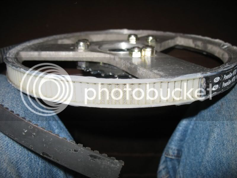
Here's the link to find AussieJesters cast pulley teeth. He used the HTD-5mm pitch belt as the tooth-mould, and the metal core is a V-belt pulley. He later went another way because he wanted a larger diameter pulley than this largest V-belt unit, but he stated that it worked well when he was using it in his drive.
"Turnigy HXT Powered Custom Cruiser Worklog" 104 pages
http://endless-sphere.com/forums/viewtopic.php?f=28&t=12810&start=90#p200130
I really like how the Extron Kart #219 sprockets have an aluminum spider, and the outer part that wears out is plastic. I would like a similarly designed large pulley with a 12mm bore (can be easily bored more to 1/2-inch if wanted), and the 6-hole kart sprocket standard should be used to mount the pulley-teeth ring.
spinningmagnets
100 TW
Edit: after some reading, these makerbot 3D printed parts have a very rough surface finish, and they are intended for light duty. Higher quality 3D printers are many times more expensive due to a smaller nozzle and a finer series of movements than these coarse units...
I found that the makerbot thingverse has already been making 3D printed pulleys for expensive or non-stocked or hard-to-find sizes. I want a 12mm bore, HTD-5mm pitch, 18T, 25mm wide (can be easily cut shorter to fit). I don't think a flange on the outer end is necessary because the large pulley will keep the belt tracking properly.
What would be the best metal sleeve with a 12mm ID bore that a printed pulley could be epoxied onto? I would also like two set-screws in the fat shoulder (perhaps a roll-pin would be adequate?). Any thoughts would be appreciated...
http://www.thingiverse.com/tag:pulley

This looks like a master pulley drawing file, so perhaps most of the work has already been done?
http://www.thingiverse.com/thing:16627
More of the same type of program, but with a captive nut inside the shoulder.
http://www.thingiverse.com/thing:11256
http://www.thingiverse.com/thing:5109
http://www.thingiverse.com/thing:3104
http://www.thingiverse.com/thing:2079
Maybe its a useful option to make the pulley shank a smooth reduced diameter (reduced compared to the pic example, maybe 17mm?) and clamping force can be a common shaft clamp like this? If friction force was not adequate, a set screw can be drilled and tapped through one side of the clamp OD, through the plastic shank, and into a shaft dimple...

I found that the makerbot thingverse has already been making 3D printed pulleys for expensive or non-stocked or hard-to-find sizes. I want a 12mm bore, HTD-5mm pitch, 18T, 25mm wide (can be easily cut shorter to fit). I don't think a flange on the outer end is necessary because the large pulley will keep the belt tracking properly.
What would be the best metal sleeve with a 12mm ID bore that a printed pulley could be epoxied onto? I would also like two set-screws in the fat shoulder (perhaps a roll-pin would be adequate?). Any thoughts would be appreciated...
http://www.thingiverse.com/tag:pulley
This looks like a master pulley drawing file, so perhaps most of the work has already been done?
http://www.thingiverse.com/thing:16627
More of the same type of program, but with a captive nut inside the shoulder.
http://www.thingiverse.com/thing:11256
http://www.thingiverse.com/thing:5109
http://www.thingiverse.com/thing:3104
http://www.thingiverse.com/thing:2079
Maybe its a useful option to make the pulley shank a smooth reduced diameter (reduced compared to the pic example, maybe 17mm?) and clamping force can be a common shaft clamp like this? If friction force was not adequate, a set screw can be drilled and tapped through one side of the clamp OD, through the plastic shank, and into a shaft dimple...
spinningmagnets
100 TW
3D printing pulleys for the GNG kit starts around this post by "bee" in the very long GNG thread, and info is scattered over the next few pages in between other discussions.
http://endless-sphere.com/forums/viewtopic.php?f=28&t=42785&start=1325#p700886
Also info in the "world domination, I got a 3D printer" thread, here:
http://www.endless-sphere.com/forums/viewtopic.php?f=1&t=42259&start=400#p708222

http://endless-sphere.com/forums/viewtopic.php?f=28&t=42785&start=1325#p700886
Also info in the "world domination, I got a 3D printer" thread, here:
http://www.endless-sphere.com/forums/viewtopic.php?f=1&t=42259&start=400#p708222
1000w
1 kW
spinningmagnets said:Here's the link to find AussieJesters cast pulley teeth. He used the HTD-5mm pitch belt as the tooth-mould, and the metal core is a V-belt pulley. He later went another way because he wanted a larger diameter pulley than this largest V-belt unit, but he stated that it worked well when he was using it in his drive.
"Turnigy HXT Powered Custom Cruiser Worklog" 104 pages
http://endless-sphere.com/forums/viewtopic.php?f=28&t=12810&start=90#p200130
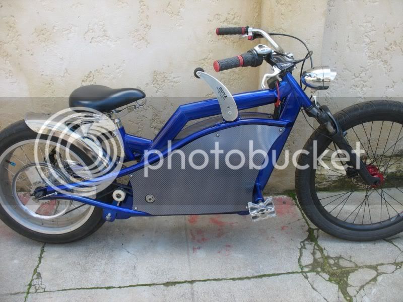
This is the original post by myself for those that may want more detail. Kim was posting photos of a pully I made for a Cyclone powered cruiser.
http://endless-sphere.com/forums/viewtopic.php?f=6&t=10337
spinningmagnets
100 TW
Thanks for clearing that up, mate! The extra-detail photos are wonderful, and very helpful. Your Blue Cruiser is absolutely stunning! Has the epoxy-teeth pulley held up well over time?
1000w
1 kW
Thank you for the kind words and for your many many helpful posts.spinningmagnets said:Thanks for clearing that up, mate! The extra-detail photos are wonderful, and very helpful. Your Blue Cruiser is absolutely stunning! Has the epoxy-teeth pulley held up well over time?
I sold the blue bike a fair while ago and haven't seen it since. I did however clock up a bit over 2000km and the epoxy teeth showed no wear.
I think the method works so well on a large pulley as the load is shared by many teeth at once.
Cheers,
Matt.
bandaro
10 kW
Also guys, don't think I reported back, but the 60 tooth pulley I cut out of 3 pieces of 6mm acetyl plastic with a laser cutter didn't work, far too much kermf in the plastic. It may work well out of aluminium or something with a higher melting point, but I couldn't get some acrylic to work either.
Edit, further discussions via pm lead us to think this may partly be due to the low power of the cutter, so if you have a big one then it may be worth testing.
Edit, further discussions via pm lead us to think this may partly be due to the low power of the cutter, so if you have a big one then it may be worth testing.
bobc
10 kW
Just made the first sections of a big (150 tooth x 5mm HTD) pulley using our home-made CNC router. It's our first foray into machining Al on the Zoltar so we were a bit tense - but the job went very smoothly. The only problem we had was the workpiece breaking loose on the final cut (we didn't make the "tags" wide enough). I'll put another pic up when we've done the whole thing - this one is a trial for the school greenpower project but it could just as well go on the back wheel of an ebike.


The toothed bit is made in 6 120degree sections (2sides) - this method uses about 20% as much aluminium as cutting out 2 full big rings
Bob
The toothed bit is made in 6 120degree sections (2sides) - this method uses about 20% as much aluminium as cutting out 2 full big rings
Bob
1000w
1 kW
Hey Bob,
Awesome work mate, looks like art to me!
Please keep us posted on how it goes.
Cheers,
Matt.
Awesome work mate, looks like art to me!
Please keep us posted on how it goes.
Cheers,
Matt.
bobc
10 kW
One finished sprocket made from sections. Looks pretty good, it will be a few months before it's used in anger.

Trilska
10 W
Looks like a good way to make a larger pully from smaller parts when the cnc mill aint big enough, mind if i steal the idea for a 80t 8mm htd pulley?
spinningmagnets
100 TW
Bobc, what is that 8-hole interface? also, what is the rim BCD of the 6 bolts that hold the rim together? Once I have the proper name (for the 8-hole), I can find various adapters that others have made, and who would make things like that.
I believe that the small pulleys/sprockets should be high-quality metal. The benefit of being able to make them with 3D printed plastic is the ability to print them out fast and cheap during the prototyping phase...when you really aren't certain yet as to what would work best.
That being said, I have always liked the configuration of having a metal spider shaft-adapter wheel-adapter that is durable and strong. Then, the sprocket/pulley ring can be made of a softer material that is easier to cut/print...since there are many teeth engaging it. If there is any slippage, it will be on the small tooth-count sprocket/pulley. I would not hesitate to use a large tooth-count pulley like this that was 3D-printed from the simple and coarse plastic, as long as the spider was aluminum.

Karts have two-piece large sprockets so that they can be easily changed from the center of an axle without removing the wheel first. For us, when contemplating large pulleys that cannot be found off-the-shelf, the sectional tooth-ring allows a smaller 3D printer to make the sections.

I believe that the small pulleys/sprockets should be high-quality metal. The benefit of being able to make them with 3D printed plastic is the ability to print them out fast and cheap during the prototyping phase...when you really aren't certain yet as to what would work best.
That being said, I have always liked the configuration of having a metal spider shaft-adapter wheel-adapter that is durable and strong. Then, the sprocket/pulley ring can be made of a softer material that is easier to cut/print...since there are many teeth engaging it. If there is any slippage, it will be on the small tooth-count sprocket/pulley. I would not hesitate to use a large tooth-count pulley like this that was 3D-printed from the simple and coarse plastic, as long as the spider was aluminum.
Karts have two-piece large sprockets so that they can be easily changed from the center of an axle without removing the wheel first. For us, when contemplating large pulleys that cannot be found off-the-shelf, the sectional tooth-ring allows a smaller 3D printer to make the sections.
bobc
10 kW
"when the cnc mill aint big enough, mind if i steal the idea for a 80t 8mm htd pulley?". Of course not - that's why it's on here. Also uses a lot less material than a big ring where you throw away all the middle.
SM the 8 bolt interface is to sit on a standard 16tooth freewheel. To be honest this system is only cheap if you happen to have access to a suitable mill.... The original idea for milling a toothed belt pulley this way in 2 halves came from "zoltar" on here, & I made one of his machines last year.
SM the 8 bolt interface is to sit on a standard 16tooth freewheel. To be honest this system is only cheap if you happen to have access to a suitable mill.... The original idea for milling a toothed belt pulley this way in 2 halves came from "zoltar" on here, & I made one of his machines last year.
Kin
10 kW
What is a sprocket like Bobc made roughly worth to people? I could try and print it out of PLA on the teeth, bolted to aluminum or steel for the spoke-like members. Eventually I could do ABS but for now my print chamber can't do larger than 4" ish ABS pieces without warping or more effort than can be afforded for scaling.
Smaller sizes can be printed in Nylon, but that filament is a good bit more expensive.
Smaller sizes can be printed in Nylon, but that filament is a good bit more expensive.
bandaro
10 kW
Good to see someone has had success with this method, I have been considering doing this simply to allow an easy fit/replace for a slipper. It was either this or cut down a regular aluminium one you buy to fit my use.
I will try cutting a gt2 sprocket, 72 tooth 5m pitch out of a 12 gauge aluminium centre and some acrylic rings (unless I find my acetal, but I use acrylic in the laser cutter so have it on hand) to go on the outside, cut it in one big ring as it's a cheap material. If I am using a cnc router to cut it for a 15mm belt, will 8mm plastic be strong enough or should I use 3mm with a layer of aluminium in between, so 3mm plastic, aluminium, p, aluminium core, p, a, plastic again to make up the width? Any thoughts on this method guys?
Kin, I have full workshop access, so not a great deal personally, but I would be more interested if you made a mould and could do a form of injection moulding to get it all in one piece, possibly from a better material than pla.
Similar threads
- Replies
- 29
- Views
- 6,539
- Replies
- 5
- Views
- 2,150
- Replies
- 1,555
- Views
- 272,753