BIG BLOCK alternative Motor

You are rigth I just completely forgot about electrolysis problems with high voltage and current with a high water content coolent mix... better stick with transformer oil haha I don't want to transform my motor in a big hydrogen bomb :shock:
 
Hey Guys,

Loving the new ride BZH.. and this discussion about added cooling 8)
One factor I'd really like to see altered, for heat generated comparison,
is gearing. Not sure Adam how easy it would be to up the volts and reduce
the final drive..? I'd imagine a performance upgrade for sure, but would
really like to see if temps could be brought back to within reason with the
lower amp draws?
Kudos!
 
Did anyone bother to read the thread link of the Russian guy running the Cyclone at 5kW with only air cooling ?
It seems that with a little assisted air flow, dramatic cooling improvements can be realised.
Must be better than messing with motor internally.
 
yep, the high airflow one is really an option too. The "tiny" fan must not be tiny. Even if we use a 20W for a fan... we are better in efficiency as if we loose 80W by fluid friction. The fan does not run always of course. The 5.8kg we have should be ok, we just need to move away the heat accumulated in these 5.8kg. Guess it can do 100A for 1 minute, that is all we want! so we need to cool it down in the following 2-3 minutes of >30A use.

So both solutions somehow make sense, but if we have the possibility to easily (and efficiently) use air cooling we should use it. The Direct Drive guys dont have that option without revealing their motor internals to the ambient dust of the track (dust is absolute the enemy of motor internals)...so they surely prefer oil cooling over flow-through air cooling if they care about reliability.

Maybe air cooling is load.. we have to silence it. A radial fan at the back end makes lots of sense to me.. it could be temperature controlled, cheap and easy to swap out (if it fails due dust). In addition, we can enlarge the heat path to the fins with epoxy between copper and stator lamination.
 
What about just cutting some holes into the side plates and mounting a alternator fan behind the sprocket to pull air through the motor? Sure you would have to clean the motor every so often but unless you are riding in a dust storm I doesn't seem like it would be so bad.
 
I think the 10-20 W external centrifugal fan makes more sense as you can keep it blowing when the motor is stopped but the heat is still "soaking" into the case. As has been said, this is the way big industrial DC motors are cooled.
images


Or how about something like this used on RC motors ( $14 )
http://www.integy.com/st_prod.html?p_prodid=14850#.U36aNyjke8A
C24495.jpg
 
Its worth a go. Lots of science going on overnight :mrgreen:

What I'd had in mind was sandwiching the 80mm wide casing between side plates, and maybe going back to crossbreak's original 100mm fatbike BB proposal on page two.
Clamp.png


I wasn't joking about peanut oil BTW, its common in cheap transformers.
 
That's exactly how my motor is mounted...
 
I was trying to recall where I had seen it - thank you Whiplash you are quite right!!!
 
Hi Crossbreak, thanks for posting that photo.
2 questions:
1) the hall sensor circuit board is quite skewed.. are the sensors correctly positioned and ok?

2) By the sound of it, you understand motor theory well. I know a little, but would appreciate your comments (and from others who understand motors better than I do).. Industrial three phase motors often have all 6 winding ends brought out, and are connected in Star for startup and delta for full speed running. I know that the current draw, ideal voltage and torque characteristics are different with the different connections.
Could there be any benefit in disconnecting the winding ends at the star point and bringing all six ends out, and (either electronically or mechanically) switching between star and delta while riding?
I am wondering if this could create electrically a "Two speed" characteristic similar to having a mechanical two speed gearbox, making a single speed direct drive system more versatile.

If there was any theoretical advantage, could it be done with a standard controller or would it need a special controller (or 2 controllers?)?

Thanks in advance,
Dave
 
sure you'd have an: advantage. You could use two different KV, use your controller more efficiently. But as controller loss is small, our builts are mostly overpowered anyway, i dont think this is very reasonable. The effort is simply to great.

If this thing runs fine in Delta is something we have to test. If this motor is not wound like 99% perfect ( uneven phases) you always get "leaking" currents which lower efficiency. I dont know much about motors either, so i can't tell what really matters here. I tried that with the bafang BPM and had additional loss of ~7%. That was simply too much for my taste so i switched back to WYE. Maybe it's different with this motor, something you can only know if you try.

All 6 leads are soldered, to connecting it in Delta can be done with an effort of about an hour if you now how.
 
you need to change hall position in Delta, which i never tried...always used sensorless operation with these modded motors.
I tried this with a Clyte HS3540 ( you can reread there) which worked much better than with the Bafang...really no clue why.


Edit:
did that Delta conversion... weird results. In Delta it seems to have lower no load consumption then in WYE !??!? WTF?? How can that be??

I have to double check my measurement...

Link to Star-> Delta-Mod Tutorial for "big block alternative motor" http://www.endless-sphere.com/forums/viewtopic.php?f=30&t=36767&p=899498#p899498
 
this is what i got:

46.2V Delta: 134W 2589 rpm
46.3V Star: 75 W 1500 rpm
79.2V Delta: 340 W 4440 rpm (lol this sounds nice 8) )
79.7V Star 135 W 2582 rpm

Seems that this one runs fine in Delta. Both Delta and WYE consume the same no load power at ~2590rpm. The rpm are calced by KV, didn't measure
 

Attachments

  • 46.2V Delta 134W.JPG
    46.2V Delta 134W.JPG
    118.7 KB · Views: 6,829
  • 46.3V Star 75W.JPG
    46.3V Star 75W.JPG
    122 KB · Views: 6,829
  • 79.2V Delta 340W.JPG
    79.2V Delta 340W.JPG
    113.7 KB · Views: 6,829
  • 79.7V Star 135W.JPG
    79.7V Star 135W.JPG
    99.6 KB · Views: 6,829
Wow,
Thanks for the amazingly prompt and detailed response to my question, Crossbreak!!
I agree that if we get as much performance as we need in Star, there is no point in modifying the motor or making the system more complicated. However, that information might be useful to someone in future.

Interesting that the power consumed at the same speed is identical. I assume that the efficiency of the motor in star and delta is the same, which is good.
Dave
 
sure. This motor can be used with good power at 48V now. I like 48V systems more since you can touch 48V without any pain...which is not true for 74V or 96V. This makes insulation and wiring easier..IMO below 4kW higher voltages than ~60V make not much sense...but we often have to use it since most motors are wound too slow to get some serious power from them...and many suffer from lower efficiency in Delta. Also, MosFETs can take the most power in the range of 70 to 100 Volts.

Anyway, i'm really thinking about 48V again now. BMS gets also cheaper then, and simple plugs like XT60 ant HXT that are not really "touch proof" can be used safely at this voltage level.
 
Great info - thanks Crossbreak. Looks like a 6203 series bearing in there as well..
 
My BHT 1kW motor has arrived!

A few fins slightly bent but no significant damage.. the box was still in good condition.

It took about 15 days to arrive to my small town in New Zealand from date of order. The parcel was dispatched from Malaysia by DHL express.
99 Euro for the motor and 84.56 Euro for the freight. It came through NZ customs unmolested and free of duty.

I put it beside my wooden model, and was pleased to see that it was slightly smaller than the model, so should fit ok where I planned.
Unfortunately I do not have enough spare time to get out to the workshop and mount it immediately, but hopefully I will make some more progress soon.
2014-07-04 21.30.10.jpg

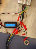
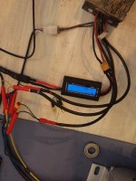
I will try to connect it to the Kelly controller, program the Kelly for very low maximum current and slow throttle response, connect 4 12V gel-cell lead acid batteries in series and see what happens! I might be able to learn something about programming the Kelly, and be able to figure out the correct connections for the Hall sensors.
Alternatively I have a 24V, 10A DC power supply I could try, if the Kelly is happy at that low voltage.

Also: I plan to fit a 16 tooth 219 chain sprocket to the motor. One option I am considering is to simply bore out the 16 t sprocket to a press fit on the teeth of the BHT supplied sprocket and TIG weld it in place. I might have to machine down the OD of the BHT sprocket a bit first.
I have done similar things before, with success, but can anyone see a reason not to do it this way?
Do you think the standard sprocket bore and keyway can take the torque of the motor at 100 plus amps?

The only stronger alternative I can see is to strip the motor and machine a keyway in the 18mm diameter portion of the shaft, which I could do, but it is a bit of extra work.
 
Man that is cool. Tempted to do something similar still with it wedged between the aluminium frame. Better check out that thread and see if they are still doing a reduction between it and the rear derailleur given the standard bike chain in use...
 
Back
Top