BionX R320/R420 RIDE+ | over-voltage/temperature

mhoekstra

1 mW
Joined
May 13, 2019
Messages
10
I have a BionX R320/R420 RIDE+ battery (01-3852) 48V/6.6Ah 316.8Wh.
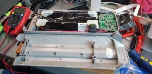
20190819_121906-2.jpg

Now when I charge it, I hear the 2 beeps, the orange light is not lighting-up, but the Green light is lit continually.

I see power is going in (the charges takes 70 to 90 watt, but is it stops charging after a few minutes and then the green light is blinking green slowly.
Somewhere I found out this is due to over-voltage of over-temperature.
At least over-voltage is not the case in my opinion, since the battery pack is only 50.4V.
Also the cells (parallel groups) read 3.73V to 3.84. Not too much out of balance I guess.
Also I don't see the battery-pack itself getting warm with my FLIR.
What I see is that one big component on the electronics board is getting warm (the WE 74435573300 / T1601), but I guess this is not necessarily bad I guess.

I also have measured the 2 temperature sensors that are going to the pack and they both read 9.5 (on 20k) resistance.

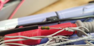
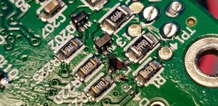
The only thing I can find that is really broken is one really small resistor (SOT-323?) with the marking 1P5.
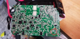
20190819_173059-2.jpg
20190819_131215-2.jpg

I want to replace this, but can't seem to find this component so I don't know the specifications.
Also I wonder if this component is not just to light a LED.

Hope anyone can help me with some debugging.
 
mhoekstra said:
The only thing I can find that is really broken is one really small resistor (SOT-323?) with the marking 1P5.
It's probably a transistor. But...it's tough to find the actual part used just by the number on it, because the same code can mean several different devices. :(

This *might* help, but it doesn't always.
https://www.sphere.bc.ca/download/smd-codebook.pdf

Also I wonder if this component is not just to light a LED.
Does it trace out on the circuit board to one?

FWIW, it's pretty smashed; that won't happen while it's just operating inside the case. It would get broken from a mechanical impact of some type. I can't tell for sure, but it looks like the conformal coating evenly coats the broken bits as well as the board under where the part would've gone, implying it's been this way since it was built at the factory. You can use a UV light to make the CC glow to verify this.

If it was, then if this problem is new, it's probably not causing it.


When you measure the cells, is it while the charger is running? Or after it's stopped? Because high internal resistance in them (or somewhere else) could cause voltage to spike while current is flowing, and perhaps cause the error.
 
amberwolf said:
mhoekstra said:
The only thing I can find that is really broken is one really small resistor (SOT-323?) with the marking 1P5.

This *might* help, but it doesn't always.
https://www.sphere.bc.ca/download/smd-codebook.pdf

Also I wonder if this component is not just to light a LED.
Does it trace out on the circuit board to one?

FWIW, it's pretty smashed; that won't happen while it's just operating inside the case. It would get broken from a mechanical impact of some type. I can't tell for sure, but it looks like the conformal coating evenly coats the broken bits as well as the board under where the part would've gone, implying it's been this way since it was built at the factory. You can use a UV light to make the CC glow to verify this.

If it was, then if this problem is new, it's probably not causing it.


When you measure the cells, is it while the charger is running? Or after it's stopped? Because high internal resistance in them (or somewhere else) could cause voltage to spike while current is flowing, and perhaps cause the error.

Thank you so much for your extensive answer!
I'm almost certain that the transistor is for the orange light on the charger port. Still have to trace it exactly.

Actually I want to test the pack with my Hyperion 16S charger. Do you think I can disconnect the pack from the electronics without it getting locked or something?
This way I'm going to check if it's not just the cells and hopefully all the electronics are still good (except for the small transistor)
 
mhoekstra said:
Actually I want to test the pack with my Hyperion 16S charger. Do you think I can disconnect the pack from the electronics without it getting locked or something?

I don't know. Some OEM packs (dunno about BionX) brick the electronics completely if anything is disconnected, even accidentally or an internal failure. You can check the vairous Bionx threads around here to see if anyone has posteda bout yoru particualr pack or not, at least.
 
I believe the Makita pcb's are like that. If one gets to low, the pcb shuts down and is bricked.

amberwolf said:
I don't know. Some OEM packs (dunno about BionX) brick the electronics completely if anything is disconnected, even accidentally or an internal failure. You can check the vairous Bionx threads around here to see if anyone has posteda bout yoru particualr pack or not, at least.
 
I'm a little further in the testing-proces...
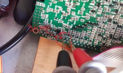
There is a resistance of 13.4 kOhm between the ground (first wire of the flat cable) and the second wire of the flat cable.
This was broken and indicated completely different values. I put a new resistor in between, but unfortunately the battery still stops charging at 50.4V. I now doubt whether it has to do with the voltage or the temperature sensors.

I also measure 4.69 kohms on each of the 4 NTCs.
I measure 1 (ground) <-> 3 (NTC1), 1 <-> 4 (NTC2), 1 <-> 5 (NTC3) and 1 <-> 6 (NTC5)
As already mentioned, I measure between 1 (ground) and the second 13.4K ohm

20190826_174548 (1).jpg
20190826_181622.jpg
 
I'm also balancing the pack now with my ISDT BG-8S.
The Pack was imbalanced with +/- 100mV. (is this still ok?)
Maybe later I will charge it to arount 54V with my external Li-Ion charger.

All the time I keep the pack connected to the electronics-board/BMS, just to be sure
 

Attachments

  • 20190826_183914.jpg
    20190826_183914.jpg
    116 KB · Views: 507
Is there anyone who knows how much ohm the NTCs / thermistors in this BionX battery contain? I measure less than 5 kohms (in the active circuit) for each of the 4, but many standard NTCs are 10 kohms?
 
To measure an NTC, it has to be disconnected at one end from the circuit, or you are measuring the whole circuit's resistance.

It also should be at "room temperature", usually 72F, AFAICR. Other temperatures will give different resistances (that's how they work).
 
Back
Top